Deep Tech: Trail Camera Firmware Hacking 5 — Trigger to Image Capture
What happens between the time that a trail camera “triggers”, takes its first image, and goes back to sleep? The answer to this question must be seen in the context of the critical resource for trail cameras: battery power. This priority affects the very foundations of the design. The “trigger to capture to sleep” sequence, and the efforts that the trail camera designers take to reduce the trigger delay, are critical to understanding how the camera “works” . In this post, I focus how a trail camera takes a picture/video. This post is part of a multi-part series. See Deep Tech: Hacking Trail Camera Firmware 1 — Overview for context and pointer to other posts in this series.

Sequence for Taking Photos/Video
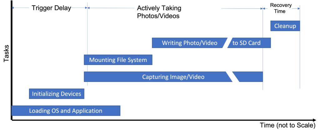
The diagram below shows the sequencing of tasks in time required to take photos and videos. The rest of this section covers each of these tasks in more detail.

In the Beginning, there was Darkness
Almost all of the time, the main components of the camera are turned off. This includes program memory, the image sensor, the image processing pipeline, the LCD display, etc. The only things left “on” are the PIR sensor itself and real time clock to keep track of the time. This and a small logic block needed to “wake the system up” on a signal from the PIR sensor. In this state, the camera consumes virtually no power — typically less than 1 mW.
Loading OS and Application into Memory
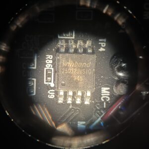
When an external event, like a trigger from the PIR sensor, happens, the camera wakes itself up. It starts by “booting” itself — that is loading the OS and trail camera application. It does this by copying a several megabyte image from an EEPROM (which maintains all of this information even without power), into system memory in the SOC. As soon as critical portions of program are loaded, the microprocessor(s) in the SOC starts executing out of memory.
Initializing System Devices and Executing Application
The program, in turn, initializes all of the critical pieces of the SOC. It also initializes external devices like the image sensor, IR Flash (if necessary), and SD card. When all this is done, the program figures out what it needs to do next. Options include taking a photo or video, or merely turning on the LCD and showing the camera menu interface.
Capturing Photo/Starting Video
As soon as the necessary devices are available, the camera starts capturing photo or video data. Camera manufacturers try to get this to happen as soon as possible, since this constitutes the “trigger delay” of the camera. Note, for example, in these Browning cameras, the firmware starts capturing image data well before the file system on the SD card is mounted, and even before all the application has been loaded from EEPROM.
Mounting SD Card File System
Eventually, the firmware needs to write the JPG or MPEG file to the SD card. This means “mounting” the SD card file system. Because the book-keeping required to initialize the file system requires reads of the SD card itself, this task takes a while. This means that although the firmware starts when the camera wakes up, it does not finish until 100’s of milliseconds after the the data from the image sensor starts. During this time, the camera buffers the current image or video stream in local memory.
Writing Photo/Video to SD Card
Even as the SOC is accumulating the JPG or MPEG data stream, the firmware must open a file on the now mounted SD card to store the image data. This may involve creating a directory or two, which involves updates to the file system. Any write errors that occur during directory creation can result in a corrupted file system. Indeed, I eventually found this type of error at the root of bug which sometimes corrupted SD cards. See Fixing Browning Edge, Elite HP4 and HP5 SD Card Corruption.
Once the correct destination directory is available, the firmware starts emptying the image/video data out of memory into the SD card. For videos, the write speed for the compressed video stream is faster than the capture rate. Thus, even though the capture of image/video data starts before the file system is available, by the time even a short video has ended, the SD card has all but “caught up” to the incoming data stream. This is critical in reducing the camera’s “recovery time”.
Cleanup
After the JPG or MPEG file is written, and the current capture is over, the firmware does a few book-keeping tasks off of the critical trigger path. This includes updating local non-volatile structures that will be used to initialize the camera during the next trigger; and making any updates to the internal configuration file stored in one of the two local file systems. In addition, all the open file system need to be “synchronized” to non-volatile storage in preparation for their being closed. This task is done fairy quickly (~100ms), enabling the camera to rapidly trigger again, minimizing so-called “recovery time.”
Back to Sleep
After all the necessary internal state has been updated, the SOC and most other systems in the camera, including the image sensor, and EEPROM are powered completely down.
Implications of Trigger Sequence for Reversing
EEPROM Updates Necessary
In terms of a reverse engineering requirement, all this means that we must somehow modify the firmware image stored in the EEPROM. Merely changing the program or data in the SOC operating memory is nearly useless, since this information is lost every time the the power is turned off. Or every time the camera is is between triggers. There are two ways of doing this: by physically replacing the EEPROM; or by using the camera’s firmware update system to update the EEPROM indirectly.

An ability to replace the EEPROM is handy during code development. It’s surprisingly easy to introduce bugs which crash the firmware before the the firmware update function can be invoked. But, for eventual firmware distribution, loading the EEPROM through the firmware update mechanism is still required.
Time Critical Code First
In the latest, Browning models the camera starts executing time-critical code out of the SOC DRAM even before all the firmware image is loaded. I discovered this optimization by trying to execute late-appearing function early in the the image capture sequence. I was initially flummoxed when fimrware mysteriously crashed because the memory had not yet been initialized.
Faster EEPROM Clock Speed
Over time, Browning has also increased the frequency, and therefore bandwidth, of the EEPROM interface. This allows the firmware image to be loaded in less time. Unfortunately for us, these higher data rates make it more difficult to reliably capture a trace of the EEPROM pins with a logic analyzer.
Removing Unnecessary Code/Functions
They have also pruned down the size of the firmware image itself by removing unused code. For example, the earlier Advantage cameras supported a command line interface through the debug TTY port. The command line interface contained all sorts of handy functions useful for testing, diagnosis, and reverse engineering. For example, functions that allowed dumping areas of the processor memory into a file. These functions were largely removed in later models, achieving a reduction in code size of about 10-20% (about 1 Mbyte).
Feedback and Coming Attractions
If you find any mistakes in this post, please let me know in comments section below.
In the next installments in these series, I’ll describe a set of 3rd party and home-grown tools which have helped in this reverse-engineering project.

Comments
Deep Tech: Trail Camera Firmware Hacking 5 — Trigger to Image Capture — No Comments
HTML tags allowed in your comment: <a href="" title=""> <abbr title=""> <acronym title=""> <b> <blockquote cite=""> <cite> <code> <del datetime=""> <em> <i> <q cite=""> <s> <strike> <strong>