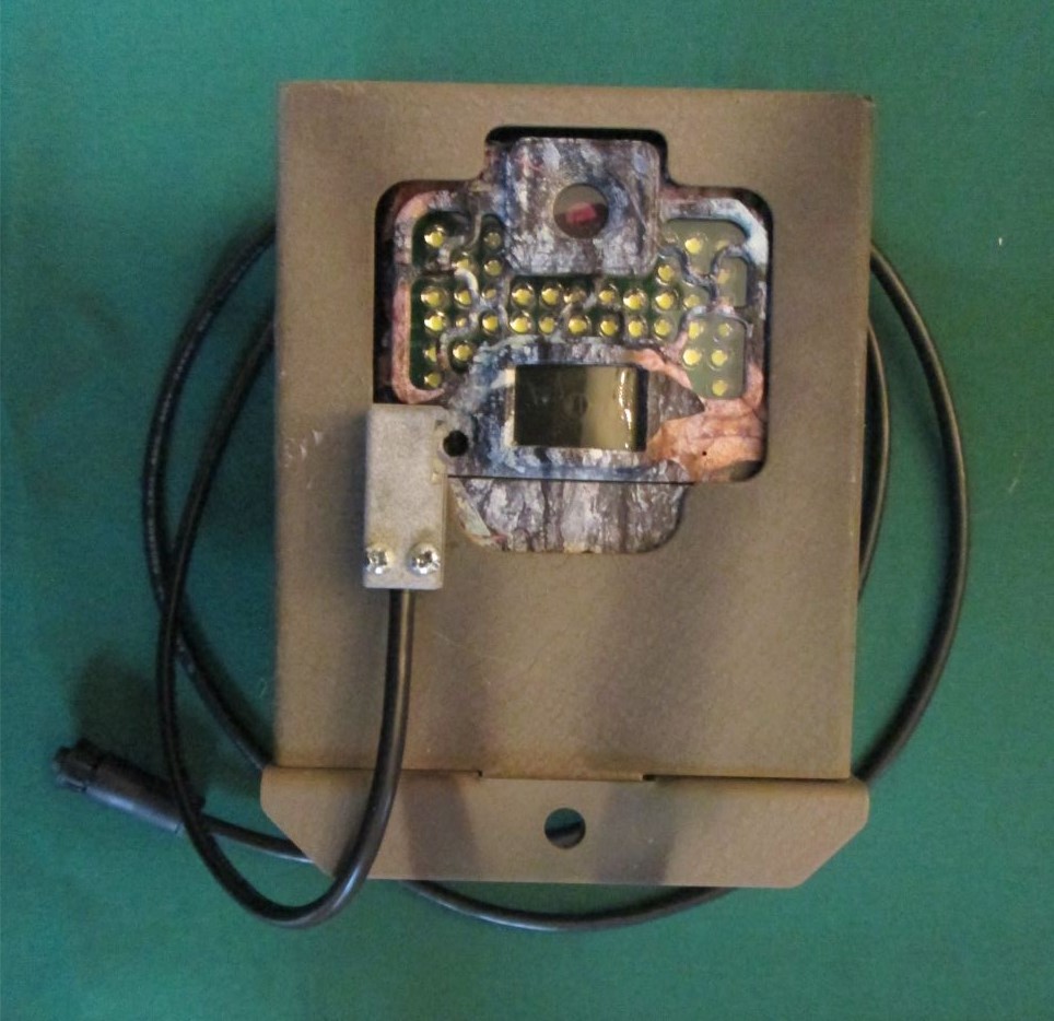
This page gives “how to” instructions for using a Browning Recon Force Advantage (BTC-7A) Trail camera to trigger a DSLR camera. For more background, see my post Using Trail Camera to Trigger a DSLR Camera
I assume readers of this page:
- are proficient with a soldering iron. If not, there are lots of tutorials online
- have a soldering setup
- have a set of small tools for electronic repair (e.g. screw driver, small pliers, diagonal cutters etc.)
I am indebted in this post to Bernardo Segura Silva and John Axtell, both of whom worked with earlier (less clear) versions of these instructions and contributed photos to help make the instructions more clear. I have done my best to incorporate their feedback. Please add your suggestions in comments, below.
Updates
2025-01-31
It’s been a while since this post when active. Here a few changes:
- Base Trail Camara: Although the BTC-7A is no longer available, I have ported a “DSLR Trigger” feature to newer models in the Browning ReconForce and SpecOps line, including for BTC-{7,8}-{E, E-HP4, E-HP5}. You can find this firmware at my GitHub site. When active, this setting causes the aim test LED to illuminate during photos and videos, as described in the original post. Unfortunately, Browning moved the AIM test LED over to the other side of the camera, so the 3d printed enclosure in the post below doesn’t work for these cameras (it blocks the light sensor).
- Photo-transistor: The NTC-3036 Photo-Darlington transistor I used for the sensor in the original post is no longer available. I believe that a standard, NPN photo transistor with sensitivity at 620 nm (red light from LED) will work. For example, the Vishay BPW16N.
Overall Solution
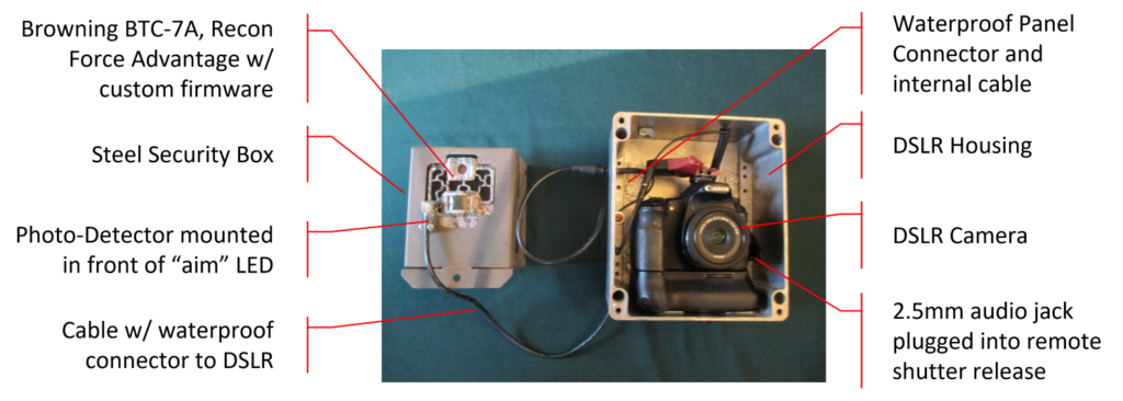
An example of the overall solution is shown in the photo below. The hardware consists of an optical sensor at the end of a cable which attaches to the camera or camera controller. Given the flexibility of DSLR systems, there are a several; of variants (so far) based on how the optical sensor is attached to the Browning trail camera, and how the cable is connected to the DSLR camera or controller. I’ll focus on these options in the next two sections.
Variants
| Connection to Trail Camera | Mounts Directly to Browning Trail Camera |
| Mounts to Security Box | |
| Connection to DSLR | Cognisys SCOUT Controller |
| Homebrew remote trigger release | |
| Homebrew DSLR Target | Canon E3 |
| Canon N3 | |
| Nikon DC0 | |
| Nikon DC2 | |
| Sony S2 |
Parts List
Note that because the different variants have different parts requirements, I have structured the “parts” list for this project into the sections which are variant-specific. Please read the parts the post . I’ve included examples of suppliers. If folks find better or less expensive suppliers, or local sources, feel free to mention in a comment and I will do my best add to this post.
Photo-detector and Cable
The key hardware for this project is a cable with a photo-transistor mounted on one side, and a waterproof connector to the camera or controller enclosure on the other. There are several variants of this cable to support photo-transistors mounted to a security box or glued directly to the Browning trail camera (for use without a security box); and for cameras connected directly, or with a a Cognisys SCOUT controller. I will walk through instructions and parts list for these options below
Waterproof Connector for Cable
There is a waterproof connector on one end of the cable. There are two options for the waterproof connector — one for connecting to a Cognisys SCOUT controller, and the other for connecting directly to a homebrew DSLR. [Sorry, I would have made these the same, except I was unable to find a source for the male connector using used by Cognisys]
Parts List for Cable and Waterproof Connector
| Part | Number | Source | Notes |
| 5-pin double connector cable | SABRE / SCOUT 5 PIN EXTENSION CABLE | Cognisys | Cognisys SCOUT controller connection: 4 or 8 meter cable with female, bayonet style Chogori 5-pin waterproof connectors compatible with Cognisys SCOUT RX input connector. For connection to Cognisys SCOUT controller, you can cut this wire in two and use the 5-pin connectors on either side. For homebrew setups, cut off the connectors (maybe with enough cable to re-use the with a Cognisys in your future?), and just use the cable (this was the least expensive way I’ve found to buy a small amount of this rugged, 5-conductor cable). You will need to install your own 5-pin connector |
If you are building for a Cognisys SCOUT system, you can use the connector already on both ends of the cable. Just cut the cable at the right distance from either connectors. We usually use a relatively short length of 4 feet or so. Make the cable longer if you want to have greater separation between the trail camera and the DSLR.
Parts List for Cable and Waterproof Connector for Homebrew Connection
| Part | Number | Source | Notes |
| 5-Pin Waterproof Cable Connector (female) | Chogori 21005211-01 | Digikey 2150-21005211-01-ND | Homebrew Connection: Note this connector is not the same as the one used in the Cognisys RX input. These have the “threaded lock ring” vs. the “bayonet lock ring” on the Cognisys. The lock ring is necessary to seal the connector. |
If you are building for a homebrew system, you will have to attach a female connector to the end of the cut cable. This is a little delicate, and is shown in the photo sequence below. I ended up building a little jig to hold the cable and the connector so that they are aligned, and so that I would have two hands for soldering.
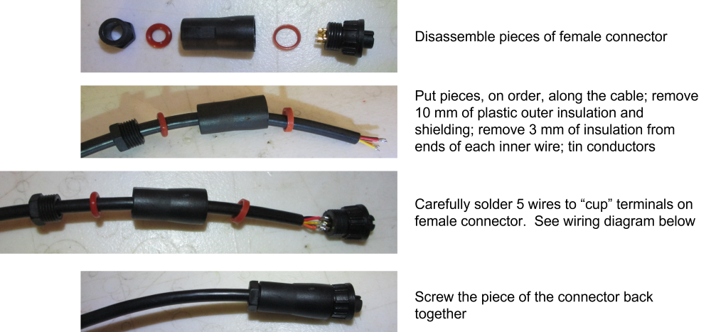
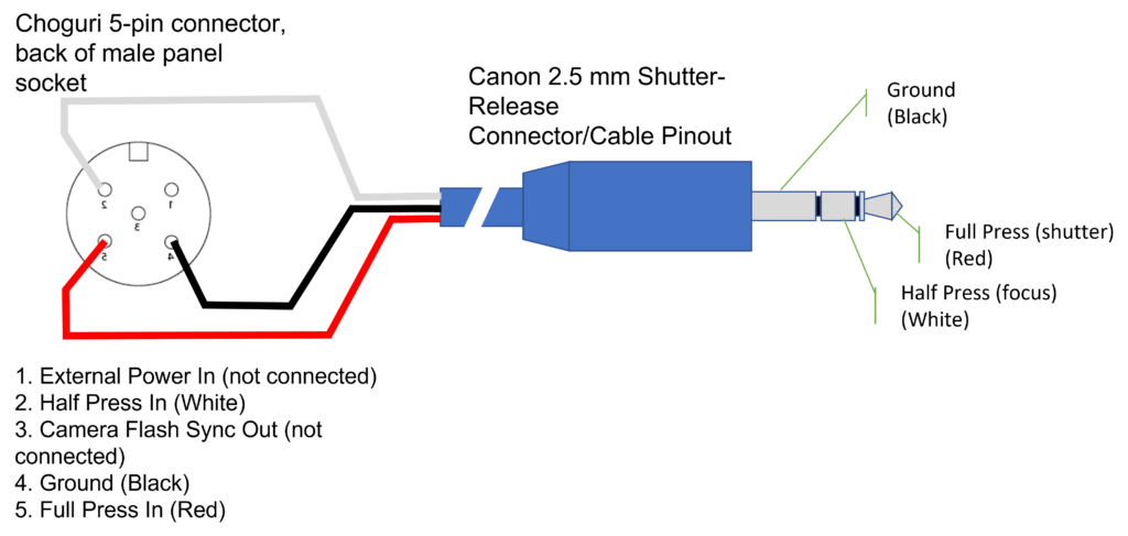
Use the wiring diagram below to connect the right color wire to the right pin on the connector.
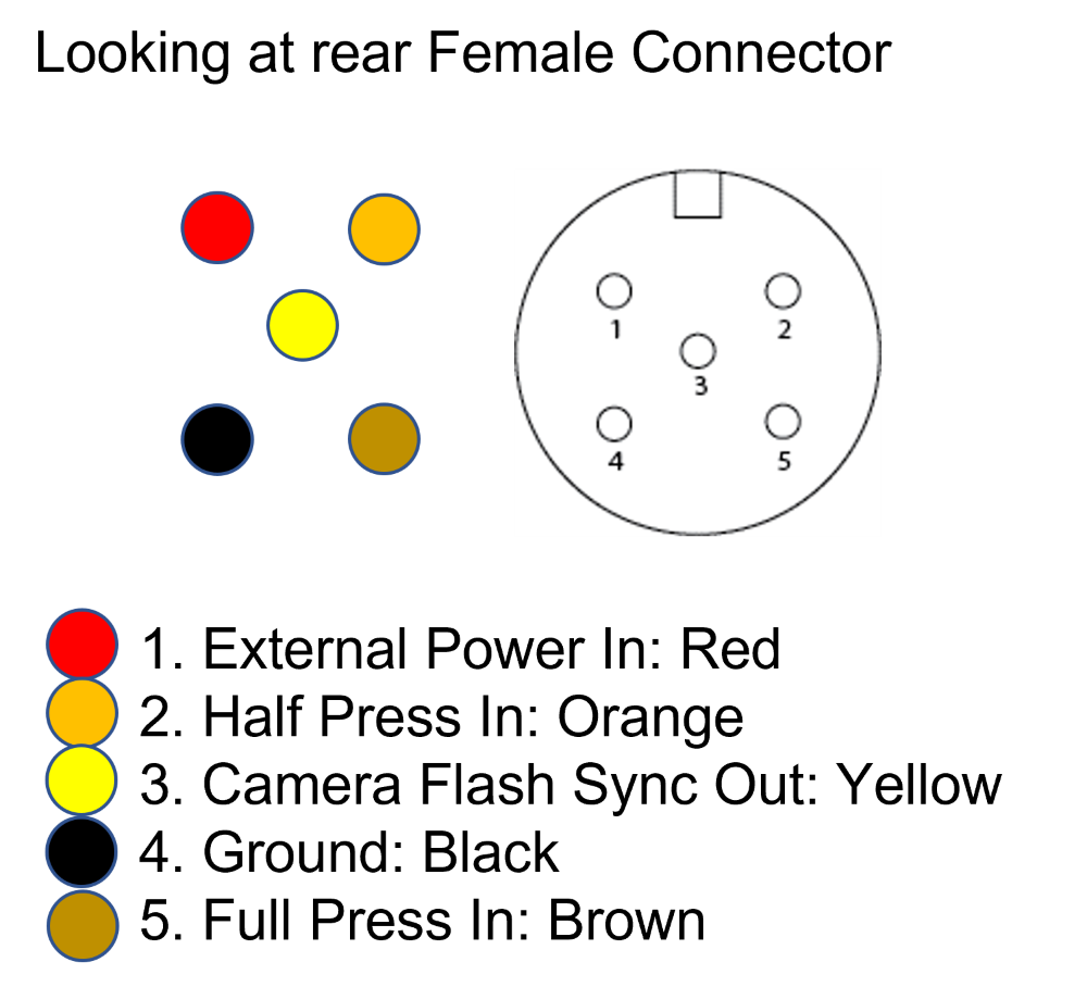
Photo Detector Mounting
This solution is based on an optical coupling between the “Aim LED” on the BTC-7A and an optical sensor. A custom firmware image causes the aim LED to come on when the BTC-7A is taking photos or videos. Because the optical sensor is sensitive to light in the visible range (to detect the red LED), it is important that no stray light “leaks” into the coupling between the LED and the optical sensor. Thus, the sensor (housed in a 3d printed housing) must be held securely against the BTC-7A camera so that it is aligned with the “Aim LED” on the camera.
It is also critically important that moisture be kept out of the small electronics cavity for the photo-detector. The electronic circuit is very sensitive, and even a small amount of moisture leaking inside can cause the photo detector to trigger the DSLR constantly.
Parts List — All Variations
| Part | Number | Source | Notes |
| NPN Photo-Darlington transistor | NTE3036 | Digikey 2368-NTE3036-ND Elliot Electronic Supply | This photo-sensor is sensitive to both visible and IR light and comes in a high gain Darlington configuration which allows it to act as a switch for the camera remote trigger input without need of any additional parts or external power supply. |
| PCB | Trail Camera as DSLR PCB | A small printed circuit board to hold the photo-transistor and attach 3 wires from the cable. I have many of these, which I’ll mail to folks while my supply lasts. Post in comments. |
Building the PCB
The small PCB to connect the photodetector to the cable. Install the NTE3016 on the front side of the board, matching the small tab on the device to the drawing on the silkscreen. Solder it in.
To attach the cable, start by removing about 10mm of the outer plastic jacket. This will expose a sheath of bare stranded wire which can be cut off. Below this is a metal foil shield, which can also be removed. This will expose 5 small gauge wires. Only 3 — Orange, Brown, and Black are connected to the PCB. Cut off the Red and Yellow wires. Remove about 3 mm of insulation from the remaining wires and use a soldering iron to “tin” the exposed stranded conductors. Once tinned, they can be inserted in the appropriate labeled (ORG, BRN, BLK) holes in the bottom of the PCB. Solder these in.
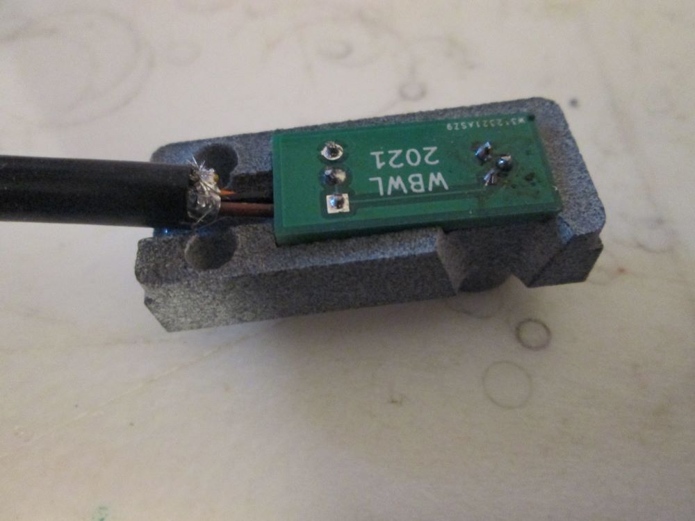
Assembling Photo Detector Housing
The finished PCB, with connected cable, fits inside the 3D printed “base plate” as shown in photo below. When placing the PCB into the cavity, smear a little liquid gasket to seal the small areas indicated in the photo.
With the PCB pressed into place, squeeze a thin bead of liquid gasket around the periphery, as shown in photo below.
Now install the cover, which fits into a slot at the top, sliding forward, and then pressing tight to the base plate, compressing the liquid gasket.
The assembly is held together by two #6-32 screws that also mount it to the trail camera security box.
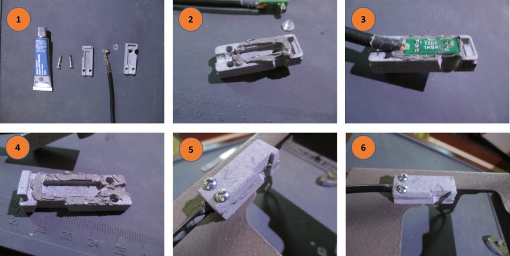
Assembling the Mounting Housing, PCB, and Cable
The first step is to install the finished printed circuit board and cable into the 3d-printed enclosure. See photo, below. The photo sensor and PCB fit into the piece with the hole, with the photo sensor in the hole, and the PCB fitted into the recessed ridge. Apply a dab of clear plastic glue around the base of the photo-transistor to keep water out.
Parts List — Assembling the Mounting Housing
| Part | Number | Source | Notes |
| Transparent Plastic Adhesive | E.g. Loctite Vinyl, Fabric & Plastic Flexible Adhesive | Amazon | This is an example only. Adhesive should be clear and flexible, and bond plastic. |

Next, complete the housing by adding the top piece. I used a thin layer of plastic glue around the edges of the PCB, and the periphery of the two 3d-printed pieces primarily to keep moisture out.
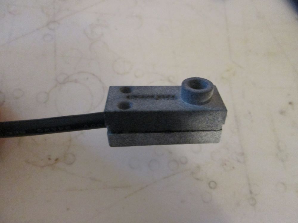
Mount the finished housing to the lockbox face plate with 5/8″ 6-32 screws. Finished product should look like photo below.
Mounting to Trail Camera
There are two ways to do this, depending on how the BTC-7A is deployed. In our sets, we almost always use a steel security box, and for this case, it’s easiest to mount the optical sensor to the face plate of the security box. In other sets (with fewer curious bears), you may want to deploy the BTC-7A “naked” (without a security box). In this case, the sensor can be glued to the access door of the camera. More detail on these two options below
Mounted to Security Lock Box

Parts List — Mounted to Security Lock Box
| Part | Number | Source | Notes |
| PhotoDetector Mounting Housing | Shroud | STL File TinkerCad Model | Links to the left for TinkerCAD model, and .STL file. Use .STL file to order the parts directly from a 3d printing service or with your own 3d printer. I used Sculpteo.com. Suggested process/material: MultiJet Fusion, Nylon PA12 (Black), not dyed. Use the TinkerCAD model if you want to tweak the design yourself |
| Security Enclosure | Browning Recon Force Advantage (BTC-7A) Security Box | CamLockBox | Steel security box for the Browning Recon Force Advantage (BTC-7A). |
| #6-32 Tap + #36 drill bit | #6-32 Plug Tap + #36 drill bit | Tap and drill for drilling and tapping holes in security box. | |
| 2 #6-32 5/8″ screws | You can find these at a local hardware store. |
The first step is to drill and tap mounting holes in the steel security box. I drilled two holes ( 0.1065″ — No. 36 bit size) in the face plate of a security box from CamLockBox.com.
To get the location of the holes right, I put a camera into the case, carefully seated it against the bottom, and put on the lock box cover. I put some double-sticky tape on the bottom of the shrouded housing piece, and then lined up the hole for the photo-sensor so that it is centered on the red “aim” LED of the camera. Note that this allows the camera’s own photo sensor (which is just to the right of the “aim” LED) to be unobstructed. Once the bottom housing is “stuck” in place, I use a small C-clamp to secure even it more firmly to the faceplate. Then I use the two mounting holes on the bottom of the housing as guides for drilling two holes in the face plate. Once the holes are drilled, you can remove the bottom face plate for assembly, or assemble it in place.
Tap the holes for #6-32 screws.
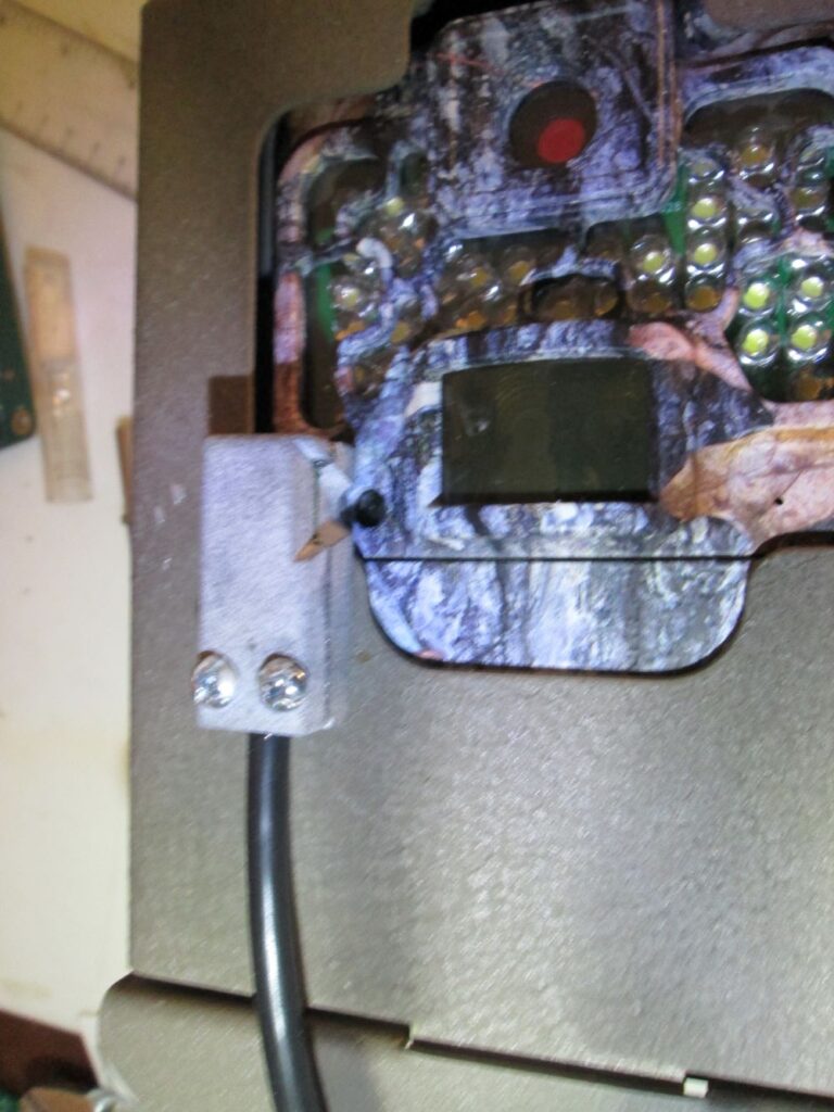
Mounted Directly to Camera
Photos from Bernardo?
Parts List — Mounted Directly to Camera
| Part | Number | Source | Notes |
| PhotoDetector Mounting Housing | Flush | STL File TinkerCAD file | Links to the left for TinkerCAD model, and .STL file. Use .STL file to order the parts directly from a 3d printing service or with your own 3d printer. I used Sculpteo.com. Suggested process/material: MultiJet Fusion, Nylon PA12 (Black), not dyed. Use the TinkerCAD model if you want to tweak the design yourself |
| #6-32 Tap | #6-32 Plug Tap + #36 drill bit | For direct mounting, drill is unnecessary, since mounting holes in 3d-printed part are already there. Still, it’s but handy to have around for future tapping projects. | |
| 2 #6-32 1/2″ screws | You can find these at a local hardware store. |
The bottom piece of the 3d-printed housing is slightly different for a the direct camera mount. The two holes in the bottom of this piece are a smaller diameter. Start by tapping these holes with a #6-32 tap.
Assemble the mounting housing, PCB, and cable as above. With two housing pieces held together, install the 1/2″ #6-32 screws into the holes of the top piece so they “catch” in the tapped holes you put in the bottom piece. Remember, this is just plastic, so don’t over-tighten!
Apply a thin layer of plastic glue to the bottom and lower part of the housing and carefully position the housing on the access “door” of the BTC-7A so that the photo sensor on the bottom is aligned with the red “aim LED”. Be careful not to cover the photo sensor just to the right of the “aim LED”. Also, take care not to let any of the glue squeeze out into gap between the door and the rest of the case.
Camera Connection
The finished cable must be connected electrically to the DSLR camera. For the Canon DSLRs installed in a homebrew enclosures, the electrical connection goes right to the remote shutter release input of the camera. Physically, I installed a waterproof connector for the cable on the homebrew enclosure, and wired it internally to the camera. In systems using a Cognisys camera enclosure and SCOUT controller, the cable connects directly to the waterproof connector labeled “RX” on the Cognisys Enclosure.
I’ll cover these two cases below
Connected Directly via Shutter Release Port
For our homebrew systems, I used the same cable configuration. I had to use a slightly different waterproof connector than the Cognisys, only because I could find it online. This type of connector has a screw-on locking ring (vs. the twist-on “bayonet” locking ring used by Cognisys). Having used both, I find I prefer the screw-on locking ring because it is easier to work with in cold weather. The twist-on “bayonet” style requires more finger torque.
I mounted the male panel connector in a new hole in the home brew case.
Parts List — Connected Dirctly to a Homebrew Canon DSLR
| Part | Number | Source | Notes |
| 5-Pin Waterproof Chassis Connector (male) | Chogori 21005515-03 | Digi-Key 2150-21005515-03-ND | Homebrew Connection: Note these connectors are different than those used in Cognisys RX input. These have the “threaded lock ring” vs. the “bayonet lock ring” on the Cognisys. The lock ring is necessary to seal the connector. |
| 2.5 mm connector with cable | 2.5 mm male plug to bare wire | Home brew connection: this will connect directly to Canon shutter release, see below for “patch cables” which can be used for other camera makes | |
| 2.5 mm Coiled Patch Cable | SmallRig Coiled Male to Female 2.5mm LANC Extension Cable | This coiled connector takes up little room inside the enclosure, but allows the camera to removed without disconnecting the trigger. |

On the inside of the home brew case, I attached a “pigtail” cable with the (Canon compatible) 2.5 mm remote shutter connector on one end to the proper pins of the male connector. Diagram below shows pinout for the 2.5 mm connector (and cable), and the 5-pin waterproof panel connector.
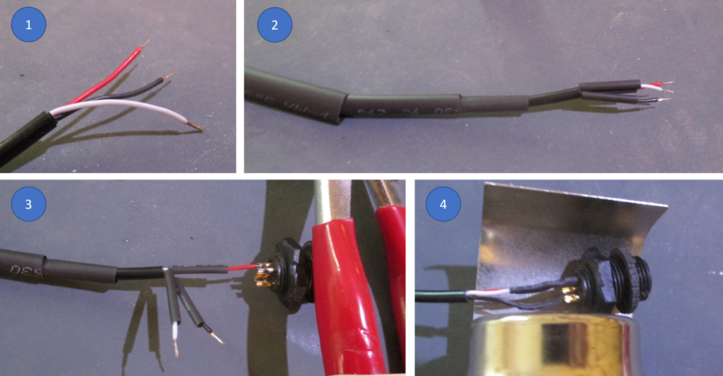
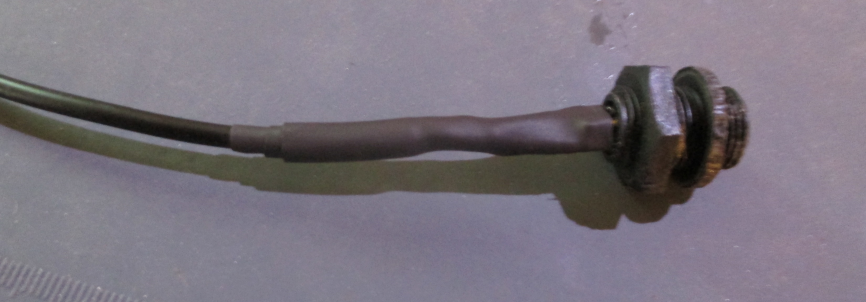
Illustrations below show the physical assembly of the pigtail. I used several layers of heat shrink tubing to provide mechanical stability, and to keep the small gauge wires from the 2.5 mm connector cable from breaking under use.
Connecting to Different DSLRs
As I’ve designed this, the signal from the optical sensor comes inside the homebrew enclosure on short cable with a male, 3-pole, 2.5 mm plug on the end. You can connect to different makes of cameras via patch cables which convert the 2.5 mm plug to the native connector for the camera. In full disclosure, I have used only the Canon 60D and 80D (E3 shutter release connector type) so far. The others should work.
| Camera Connector Type | Example Patch Cable and Adapter Sources |
| Canon E3 | Coiled Male to Female 2.5mm LANC Extension Cable |
| Canon N3 | 2.5 mm 3 pole Female Coupler Cable 2.5 mm to Canon N3 Remote Trigger Shutter Cable |
| Nikon DC0 | 2.5 mm 3 pole Female Coupler Cable 2.5 mm Remote Shutter Release Cable II for Nikon 10-pin Cameras |
| Nikon DC2 | 2.5 mm 3 pole Female Coupler Cable 2.5 mm Remote Shutter Release Cable for Nikon DC-2 Cameras |
| Sony S2 | 2.5 mm 3 pole Female Coupler Cable S2 Shutter Release Cable for Select Sony Cameras |
Secure the short cable from the waterproof connector to the inside of the homebrew enclosure to provide strain relief.
Use the appropriate patch cable (and adapter, as necessary), per table above, to go from the 2.5 mm plug to the shutter release of your favorite DSLR.
Connected to a Cognisys Scout Controller
For a Cognisys SCOUT controller setup, the photo-sensor and cable assembly can be connected directly to the “RX” connector on the outside of the camera enclosure. The SCOUT controller treats a transition, from “off” to “on” as a single trigger event. You will need to configure the SCOUT controller to do what you want with this trigger. It can do many things, including: taking a specified sequence of photos; operating in “continuous shutter mode” for a period of time; or taking video of a given duration. Consult the Cognisys documentation for instructions on setting this all up.
Testing Photo-Sensor and Cable
To test the photo-sensor and housing, cover the photo sensor (with your thumb), and connect the cable to your DSLR homebrew or Cognisys enclosure. When you uncover the sensor, the camera should trigger. This may require shining a light (e.g. from your cell phone) directly at the sensor. Covering the sensor back up should stop the camera.
Installing New Firmware
The link below contains a copy of the factory default firmware, and the new “DSLR Trigger” firmware.
This repository contains:
- /Manufacturer-Baseline/ : Firmware consistent with manufacturer install; revert to this as necessary
- /DSLR-Trigger-CR/ : Firmware that supports use of camera as a DSLR trigger. As a bonus, it also includes large (readable) date/time at the bottom of screen during photo/video playback.
- /DSLR-Trigger-WF-CR-20SD/ : Firmware that supports use of camera as a DSLR trigger, above, as well as White Flash conversion covered in IR to White Flash Trail Camera Conversion. White flash conversion is synergestic with DSLR trigger, since light from the trail camera can help illuminate the scene. We have also had some luck using this light to allow the DSLR to autofocus, even for night shots, though we do not yet a lot of experience in this mode.
Download Instructions
- Find the copy of brnbtc70.BRN file you’re interested in the appropriate folder in the repository. Click on it; then press “Download”
- Copy this file onto an SD card at the “top level” (not into a folder on SD card). You can do this without physically swapping SD card around by plugging the BTC-7A into a USB port on your computer, and copying the brnbtc70.BRN file into the folder which appears with the camera
- Note — the file must be named “brnbtc70.BRN”. Sometimes downloading from your browser will add extra characters to distinguish it from previous downloads — e.g. “brnbtc70(1).BRN”. If this happens, rename file to “brnbtc70.BRN” on the SD card.
Firmware Installation
Before installing new firmwarwe, make sure you have batteries that will easily power the camera for the several minutes it takes for firmware upgrade. Losing power during firmware upgrade is bad, requiring that it be reprogrammed by the manufacturer.
On the BTC-7A Camera
- Press “Mode”
- Select “CAMERA SETUP”
- Select “FW UPGRADE”
- Select “YES”
Display should show “UPGRADING” for about 2-3 minutes; DO NOT TURN OFF OR REMOVE BATTERIES DURING THIS TIME! (this will “brick” the camera). Camera will then “Reboot” with new firmware.
Note that firmware update will reset all camera configuration and settings, including date and time.
You can tell that firmware update is successful if you see a new picture in place of the vendor “splash” screen:.

Test your camera in video or photo mode. You should see the red “Aim LED” come on when it is taking video or photos.
Restoring Camera to Original Configuration
- To restore camera to factory firmware, follow steps above, but with an SD card containing a copy of the factory default firmware.
Troubleshooting
| Problem | Action |
| “Aim LED” does not light when taking video or photos | Make sure that you installed the updated firmware correctly by verifying splash screen is not standard. |
| DSLR does not trigger | Check that cables are all properly connected Check to see that photo sensor housing is mounted such that photo sensor is directly in front of the aim LED. Check to make sure wiring is correct. Use a jumper to connect GND and Shutter Release. DSLR should take a photo. If not, you may have wiring backwards (flipped left/right) Check that you can trigger the sensor with a small light source pointed at directly at the sensor |
| Spurious DSLR Triggers | Most likely caused by sunlight leaking into a gap between the photo sensor and the Aim LED. Debug the cause of the gap and fix. As a last resort (:( ) try a piece of duct-tape to keep the light out of the gap. |
| Continuous DSLR Triggers | Most likely moisture has gotten into the electronics cavity. Take the 3d printed assembly apart, remove excess gasket material, dry out, and reassemble, being liberal with liquid gasket |
| Firmware update menu will not highlight “Yes” as an option | Check to see that the firmware image file on the SD card is named “brnbtc70.BRN”. Sometimes browsers will add extra characters to a downloaded file (e.g. “brnbtc70(1).BRN”) to keep the name from conflicting with earlier downloads. If this happens, just rename the file to “brnbtc80.BRN” on the SD card. |
Disclaimers
- Following these instructions worked for me, but I provide no guarantee it will work for you:) I will do my best to answer questions posed in comments below.
- Note that installing non-factory firmware may void your warranty with the manufacturer. Execute this project at your own risk.
- I provide no guarantee or endorsement of suppliers listed on this page, although I have successfully used several of them with no problem.
:

Thank you for sharing these details. I’d be interested in the PCB if you still have any, but I’m in Canada. Please email me to discuss.
For connecting directly to a Canon DSLR, does the the half press need to be connected in addition to the full press? My understanding is the full press is only required to activate the shutter. I believe the half press would initiate a wake signal via the hot shoe for off camera flashes but without a small delay between half press and full press I would imagine that the flashes would not fire on the first shutter release (?)
Will contact you re: PCBs.
In my design, the photo-sensor activates the “focus” and the “shutter” functions simultaneously. As you say, this can prevent flashes from having time to get ready, and so miss the first night shot. There is probably some clever way to add a capacitor (and maybe a resistor) to slow down the activation of the shutter, giving the flashes some time to warm up. I’ll add this to my list of “puzzles” to figure out, unless someone wants to offer a solution that only uses passive components, and only power from the shutter release cable itself.
This is amazing! thanks for sharing this and all the information you post. This is an amazing blog! I wonder if you manage to make the firmware works in other camera models. I would really like to try this system but I don’t have any BTC-7A.
Thanks!
Yes! My current set of firmware hacks for the Edge, Elite HP4, and Elite HP5 (BTC{7,8}{E, E-HP4, E-HP5}) supports a “DSLR Trigger” menu item. When set to “ON”, the firmware turns no the IR test LED when taking photos or videos. See: https://github.com/robertzak133/unified-btc-reverse
There is a slight rub. For these more recent cameras, Browning moved the aim test led and light sensor over to the other side of the case. I think this means that my current 3-d printed holder for the photo sensor is mirror imaged from what it needs to be. This to avoid blocking the ambient light sensor.
Let me know if you’d like help flipping it around.
-bob
Thank you for the detailed instructions, I have been trying to do something like this using a trail camera to trigger a dslr and this looks like it will fit my needs well.
Couple questions, first, do you have a working link to the photoresistor you used? Neither of the links worked for me. Second, have you considered using an intervalometer to make the dslr take two (or more) shots to wake up the flashes? The trail camera and photoresistor would be wired to the shutter button of the intervalometer which would then trigger the dslr.
I just updated the post with a link to a new photo transistor. It’s difficult to find a BTC-7A these days. The good news is that I ported the “DSLR Trigger” feature to newer SpecOps/ReconForc models, available on my GitHub site [Earlier version of this reply included an incorrect assertion that 3d printed housing needed to be changed in TinkerCad. Not so!]
Rather than use a separate intervalometer, we typically set the DSLR up in “slow burst” mode (takes ~3 photos per second while trigger is depressed), and set the trigger cam to take 5 second videos (with a 5 second delay). This wakes up the flashes on the first photo, and takes a burst of ~15 photos. 3 photos a second is about the rate that the SB-28 flashes we use can keep up at 1/8 power. Using lower power on the flashes might allow them to keep up with a “fast burst” rate, but we haven’t tried this.
I have never used either of those specifically but I have done a little cad designing before so I’m sure I could figure out how to mirror it.
I didn’t think of the fact that you can take 5 second videos – good point that’d be much simpler than trying to hook up an intervalometer.