Repairing Browning Trail Camera that Won’t Trigger
A Facebook friend recently sent me a Browning BTC-7A (Recon Force Advantage) Trail camera that was not triggering. It was long past warranty, and Browning would not (or could not) repair. This post describes the process I went through to diagnose the problem and repair the camera. The cause of this failure was water incursion into the camera enclosure. Water and electronics do not mix, and often water damage is practically unrepairable. Fortunately, in this case, the damage was limited, and I was able to make a repair. This post also includes a companion video, below.
Confirming the Symptoms
The first thing I did was to make sure I understood what was going on with this camera. I put in new batteries, and turned it on. The LCD and menu system were both working fine. The video preview was also working, indicating that the image sensor was also working. The problem came when I set the camera to take 10 second videos, with a trigger delay of 1 second. No matter how many time I waved my warm hand in front of the camera, it did not trigger.
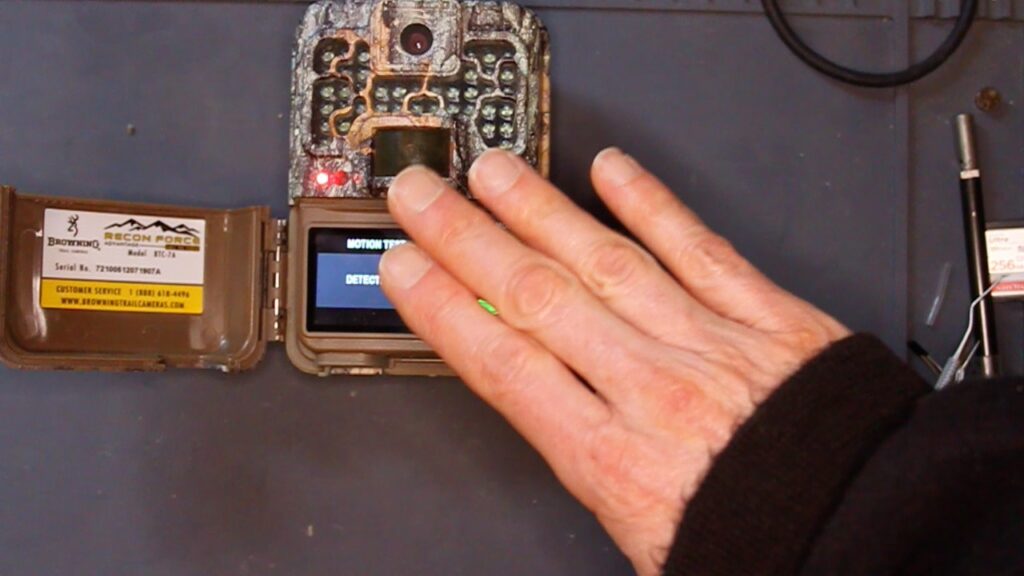
I put the camera in “Motion Test” mode. This should light the “Aim Test LED” when the PIR sensor is triggered. The “Aim Test LED” remained off, despite my trying to trigger the camera with my hand.
This data strongly suggested a failure of the PIR sensor, or the connection between the PIR sensor, and the (apparently working) main processor.
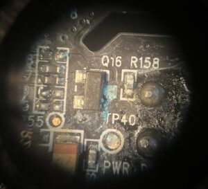
I opened up the camera, and immediately saw the signs of water incursion.
Water Damage
Water on a circuit board can react chemically with metals on the circuit board to cause them corrode. The corrosion can be accelerated if there are voltages present on the circuit board. Current flow through the water will increase the rate at which the hydrogen from the oxygen in the water reacts with the copper traces on the circuit board, and the metal surfaces of components on the board.
Metal Oxides as Parasitic Resistors
Oxidation can cause the circuit board to fail in two ways. In the first, the metal oxides created during the corrosion process may also be conductors, and can thus become “resistors” in the circuit that shouldn’t be there. Parts of the circuit board with components used to amplify very small analog signals, such as those from a discrete PIR sensor, can be particularly sensitive to the unintended addition of alternative conductive paths.
The Browning Advantage series trail camera use an “integrated” PIR sensor, in which the amplifier circuits are implemented inside the PIR sensor itself, making them almost immune to water damage. But other cameras, including the more recent Browning Recon Force and Spec Ops models, use discrete components to amplify signals from an analog PIR sensor.
Disappearing Traces
This brings us to the second type of corrosion-induced PCB failure — the failure of small copper traces themselves. When the oxygen from water reacts with the copper used as a conductor for circuit board traces, the resulting chemical conversion of copper to copper-oxides can completely consume a fine copper trace typical of modern, miniature cameras.
Cleanup
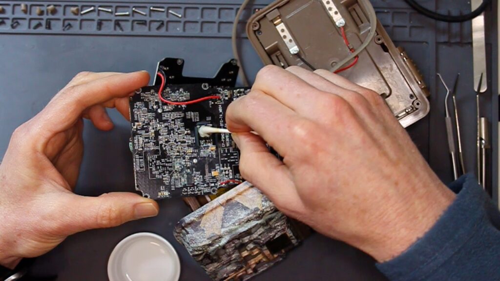
The first step in a water damage repair is to remove as much of the oxides on the circuit board as possible. I use a cotton swab and some isopropyl alcohol to do this. This doesn’t work perfectly, but it does get rid of most of the oxides.
In some cases of water damage, this step may be enough to solve the problem. Not so with this case. When I checked after cleaning the circuit board, the camera still did not trigger.
Failed PIR Sensor?
Before doing any more diagnosis work, I decided to try just replacing the PIR sensor itself. This was a long-shot, since, in my experience, this highly integrated part is quite robust, and encapsulates all the highly sensitive analog circuits required to amplify the output from the internal pyro-electric sensors. Still, while I had the camera open, I decided that I would implement my fix for “run-on triggering”(Fixing Run On Triggering in Trail Camera). This fix requires desoldering the PIR sensor, which is most of the way towards replacing it.
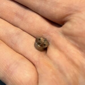
Having removed the old sensor, I put in a replacement from a parts board, and tried once again to trigger the camera. Still broken.
Diagnosis of the Specific Problem
At this point I became more methodical in my approach.
I started by verifying that the ground and 3.3V power connections to the PIR sensor were good. They were.
Serial In
Due to earlier work on this camera, a knew that the PIR sensor itself needed to be programmed correctly, so I started out to confirm that this was indeed happening. I tacked on some small copper wires to the Serial In and Direct Link pins. I then connected both to a USB logic analyzer and took a trace triggered by turning on the camera.

I could tell from the logic analyzer trace that there were indeed a series of pulses on the Serial In pin. I was able to interpret the data transfer encoded in these pulses based on the specifications for the PYD1698 part. This confirmed that the device was indeed being properly initialized.
Direct Link
I could also tell from the logic analyzer trace that the Direct Link signal was stuck “high” — that is, in a triggered state. This was clearly a problem, as this pin should be low unless the device is triggered.
I looked more closely at the specification and found that the Direct Link signal would go high on a trigger, and stay high until it was reset (by being driven low) by a microprocessor.
Testing a Theory
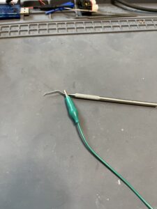
To test this, I attached a test clip to ground and to a pointy-tipped metal dental probe. I touched the tip of the probe to the Direct Link pin, temporarily driving it “low”. I verified that once I did this, the signal remained low until a passed my hand in front of the PIR sensor, which caused it go high.
As I triggered the PIR sensor, I also put the camera in the “motion test” mode, and found that even though I could see the Direct Link signal go high when I triggered the PIR sensor, it was not being detected by the camera’s processor.
This data strongly suggested an “open” between the Data Link signal and the processor. All I had to do now was figure out where the open was.
Finding the Open
A schematic of the camera in question would certainly help. Unfortunately, this is not available. But I did have a spare circuit board from another Recon Force Advantage from a previous project. I knew that the PIR sensor on this camera was working, and thus I was confident that I could use it to figure out what the correct connectivity from the Data Link signal was.
To do this, I set my multi-meter to “continuity test” mode, ready to generate a “beep” when resistance between the two probes went to zero. I put the tip of one probe to the test point on the circuit card I had discovered was connected to the Data Link signal through a working 200 Ohm resister.
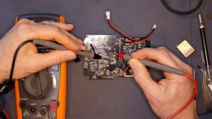
With the help of a dissecting microscope set to “10x” power, I was able to follow the thin trace (< 1mm wide) from this test point, a short distance across the circuit board, and under U15. I then methodically applied the tip of the second multi-meter probe to each of the 20 pins on this device. When I got to pin 19, the meter beeped. Now I knew that the TP52 should be connected to U15, pin 19.
Armed with this information, I retrieved the broken camera, and put one the tip of one probe to TP52. When I put the tip of the other probe to U15, pin 19, there was… nothing. No beep, and no change in resistance. I had found my open.
Repair
Now that I knew that there was missing connectivity between two specific pins — U15 pin 19, and a 200 Ohm resistor in series with the Direct Link pin of the PIR sensor, all I had to do was re-establish this connectivity.
I suspect the open in the trace itself was underneath U15. The proximity between pin 19, normally driven to a low value; and pin 20, the 3.3 Volts supply, likely caused this trace to be corroded away when a little water wicked underneath the device.
I didn’t want to removed U15. With 20 pins, this would have been tedious at best, and I might have damaged the part at worst. Instead, I carefully unsoldered pin 19 and lifted the metal pin up off the board. Then I stripped a couple of mm of the insulation off both ends of a short piece of fine gauge wire-wrap wire. I then soldered one end to the raised pin 19 of U15, and the other to the right end of the 200 Ohm resistor to the Direct Link pin of the PIR detector.
Final Test
With my repair made, I once again partially reassembled the camera, turned it on, and set it to “Motion Test” mode. I was very gratified when the “Aim Test LED” came on, just as it should, when I passed my hand over the PIR sensor. Just to double check, I also verified that the PIR sensor would also trigger the camera to take photos and videos.
Lessons Learned
The camera works now, but we did get lucky. If the corrosion damage had been more extensive, and caused multiple failures, finding each one of them would have been a lot harder. If any one of them couldn’t have been fixed with a simple patch wire, we’d have been up the creek.
I had not seen this failure before, but it all makes sense. A little water under U15, and a voltage difference between the “always one” pin 20 (3.3V) and the normal 0 V (inactive) Direct Link signal from the PIR sensor.
The best way to avoid this problem, and indeed potentially worse problems caused by water damage to electronics, is to keep moisture out of the inside of the camera. We’ve found one of the most effective ways to do this is to protect liquid water. This can be caused by the rain, melting snow, or drippings down a tree trunk, to flow over the camera case. To avoid this, we put our cameras in security boxes, which tends to deflect this water. Others have made little “roofs” which can be mounted above the camera to divert rain fall.
Was it Worthwhile?
This repair took me about 20 hours of working time start to finish. It’s possible that with a little more experience, I could get it down to 10 hours. If I actually had the schematics, and test-point data, it could be even less. Still, even if it had only taken 3 hours, this would not be economically viable as a repair business. Moreover, I might not have been able to fix the camera at all. This is true of all but the most expensive electronics these days, and explains the dearth of “small electronics repair services.” Even Browning, which could have access to design and test documents, finds it more economical to simply replace broken cameras vs. trying to repair them.
I hope this, and similar posts (How (some) Trail Cameras Fail), can help individuals repair, or at least understand, their broken trail cameras. If you think you have a similar problem with your camera, let us know in the comments below.
Great post!
Recently a number of freak downpours flooded the ranch. Water rose six feet in a canyon in a few hours.and 4 BTC 7E hp5 cams were submerged. I tried to dry a couple of them in rice but were unsuccessful. I wish I had known to use isopropyl alcohol as a last ditch effort.
A colleague had a 7E HP5 submerged 5’ under water for 2 weeks, assumed the worst. Let it rest on a sunny window sill , tray and SD removed, door open, and allow dry air to penetrate internally to naturally dry out for 4 days. Camera is perfectly working.
I’ve heard drying in rice is a myth for cellphones and not to be tried. Sorry yours failed to revive.
Wow — sound like they were lucky. Gently heating in sunlight is a good way to dry things out. I wonder if being all the way under water for so long allowed the batteries to short themselves out, thus saving the PCB. In any case, who can argue with success? 🙂
Sorry to hear about your cameras. I remember the sinking feeling of returning in the spring to a beaver wetland where we had set a camera up the previous fall on a tripod, about 3 feet off the “ground.” We paddled into the area in kayaks, and I remember thinking the water was *way* up. We were relieved to see the camera still on the tripod, but now only 3” above the water line.
Isopropyl alcohol is a good technique for removing a little oxide. But, as I confirmed, it can’t rebuild traces that have corroded away completely. With ample water, and plenty of electrical energy in the batteries, it’s likely that too much electrochemistry occurred inside your HP4s for them ever to work again.
Without the electricity from the batteries driving the chemical reactions, it’s possible that simply drying the camera out might have saved it. Unfortunately, the normal state of the trail camera is to have some portion of the camera powered at all the time, and therefore the batteries are always electrically connected to the circuit board.
One solution would be to include a “water activated fuse” in the camera, which would disconnect the circuit board from battery power in the presence of moisture. I couldn’t find such a thing off the shelf, but I did find this:
https://electronics.stackexchange.com/questions/174245/a-fuse-that-blows-upon-liquid-exposure-instead-of-overcurrent
Even if such a thing existed, and were relatively cheap, it’s unlikely that camera manufacturers would want to increase their BOM on every camera even by a few cents to cover this unlikely event. Especially when the alternative is that the customer buys another camera to replace the failed one.
This is really interesting. There is so much to learn about this hobby!
Glad you found it interesting!
Fun! Very clearly written and easy to follow.
Weirdly, I am now have a mental image of a tiny 20-legged dog raising one of his legs to pee. 🙂
Thanks, Josh. I had several mental images while I was working on this camera, when it was unclear whether the camera would ever work again. None of them involved dogs. There were several cat visits near mealtimes 🙂