Deep Tech: Trail Camera Firmware Hacking 4 — Theory of Operation
Modern trail cameras are technically sophisticated embedded hardware and firmware systems. In this post I give a description of the key components and critical working aspects of Browning trail cameras. I provide this information as background for understanding how to reverse engineer the hardware and firmware features of this camera. This post is part of a multi-part series. See Deep Tech: Hacking Trail Camera Firmware 1 — Overview for context and pointer to other posts in this series.
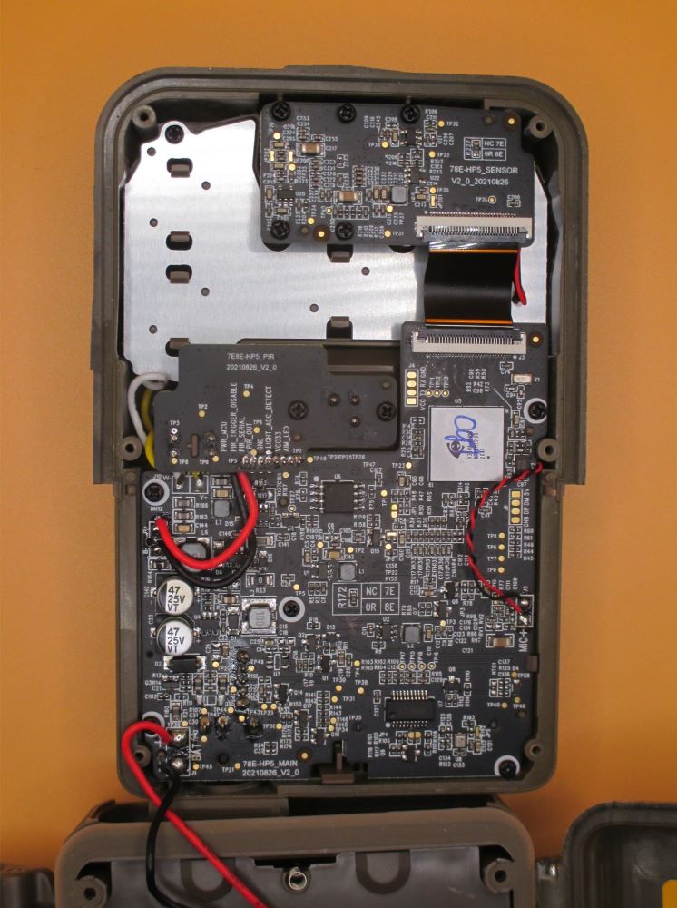
System on Chip (SOC)
The heart of this trail camera is an SOC (“System on Chip”). This device is designed especially for consumer-grade image acquisition and processing systems. This function-intensive chip includes general purpose microprocessor cores and memory, specialized hardware elements for video and sound processing, LCD screen controllers, keyboard controllers, image sensor controllers, SD card controllers, debug support, power management support, etc., etc. The term “System” on chip is no exaggeration.
The block diagram below, from iCatchTek, shows major functions and interfaces. Typical trail cameras may not use all of these.
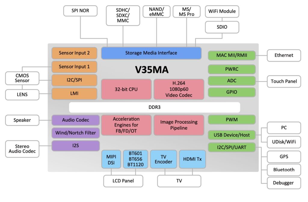
Unfortunately, this seems like the limit of documentation available for these SOC without an OEM agreement with iCatchTek. Such an agreement probably requires a commitment to purchase a large volume of iCatchTek parts, and is thus not available to the author.
Fortunately it is possible to gain some understanding of the detailed hardware interfaces for various SOC functions through the firmware. Even so, there are some blocks with complex interfaces which must remain essentially opaque.
Other Camera Elements
The rest of the trail camera consists of modules or subsystems which support the SOC.
Power Supply
The power supply takes power from either/both batteries and the external power adapter and provides the different voltages required by the camera subsystems. See Internal and External Trail Camera Power for information on how the power supply circuit draws current from both batteries and external power adapter if both are available.
The primary output of the power supply is a 3.3 Volt supply for the SOC and other devices used while the camera is actively taking images, or when the user interface is active. A separate 3.3 Volt power supply provides low current to the PIR sensor, a very small portion of the SOC, and boot controller. A third power supply gently charges a supercacitor, which provides power to the real-time clock when the batteries are removed. The IR LEDs use a fourth, adjustable, constant current power supply.
IR Flash LED
The IR Flash LEDs used in these cameras have gone through a few technology iterations to keep up with the volume market for high intensity, high effeciency LEDs. Early models were based on 5mm, discrete LEDs, whereas current models use fewer, higher intensity, surface mount LED components. See Deep Tech: Will Long Night Videos Damage the Browning Elite HP5 Trail Cameras? for a deeper discussion of the IR LEDs used in the most recent HP5 Models.
Image Sensor(s)
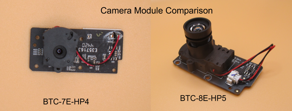
The ReconForce and SpecOps Browning models use low-light specialized Sony image sensors. These sensors have limited resolution, but excel in the low light conditions typically encountered by trail cameras. Based on my inspection of the firmware for these last three generations of cameras, all these cameras use the same 2.1 MPixel Sony StarVIS Image sensor: the IMX327
| Camera Model | Image Sensor |
| Edge BTC{7,8}E | 2 MPixel Sony IMX327 StarVIS Image sensor |
| Elite HP4 (BTC{7,8}E-HP4 | 2 MPixel Sony IMX327 StarVIS Image sensor |
| Elite HP5 (BTC{7,8}E-HP5 | 2 MPixel Sony IMX327 StarVIS Image sensor |
PIR Sensor(s)
These cameras use two different types of PIR sensors. The older models use a PIR sensor with integrated amplifier and controller. Newer models use an analog PIR sensor and a discrete amplifier with a very simple controller. Though the PIR sensor looks simple enough, in a 4-pin TO-5 package, the overall trigger sensor system is quite subtle. For a longer discussion, see: Deep Tech: Trail Camera PIR Sensors.
Microphone(s)
These Browning cameras use a single channel electret analog microphone, glued into the front case of the camera, and connected directly to the SOC through a passive filtering network. Sometimes these microphones fail, leading to poor quality audio, if not complete loss of audio. See my post Replacing Microphone on Browning Elite HP5 Trail Camera for instructions on how to replace.
Light Level Sensor
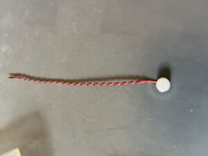
A discrete light level sensor to determines, very quickly, whether the camera has enough light to take a “daytime” or color image; or whether the IR flash is required for a “night time” black-and-white image. Once this decision is made, this sensor is no longer used. The exposure control for photos and videos is done by processing the data directly from the main image sensor.
Environmental Sensors
Both the SpecOps and the ReconForce cameras have a built-in thermometer which the use to measure “ambient” temperature. The SpecOps model have, in addition, a barometric pressure sensor. These sensors provide data used to tag photos and videos with weather meta-data.
LCD Display
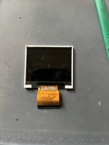
These cameras used a 2″ wide, backlit color LCD display with a VGA resolution of 320 x 640 pixels.
Keyboard
The camera gets its user input via a keypad comprising up, down, left, right and enter keys, as well as a “mode” button and the on-off switch. It is important to note on these cameras the “on-off” switch is a “soft” switch. It does not directly control power to the camera. Instead, the state of this switch is monitored by the “always on” portion of the SOC and boot controller. This controller, and some firmware, decides whether to powers up the camera.
SD Card
These cameras have a connection to an SD card slot. The firmware mounts the SD card file system on system boot. Thanks to a hardware pipeline, movies and high resolution images can be written to the SD card in real time, without the having to go through the general purpose processor. In some recent camera models, it seems that the firmware can try to operate the SD card faster than what is supported by the SOC and hardware. This can sometimes lead to SD card corruption. See: Fixing Browning Edge, Elite HP4 and HP5 SD Card Corruption
Internal File Systems
In addition to the file system stored in the SD card, these cameras have two smaller file systems, “A:” and “B:” which are backed by EEPROM. They are used to store read-only data, such as dynamic device libraries, graphic elements, fonts, and international menu configurations. These files are loaded as needed by the firmware. In addition, these file systems store user-set configuration in a file called “COLD.BIN”. This file is loaded when the camera boots. Any changes made to the camera settings are written to this file.
Any new parameters required by new features need to be squeezed into this file into bits which are not already in use. Fortunately, this file is not compressed, and data structures are not “packed”, leaving plenty of room for new stuff.
Real Time Clock and Non-Volatile Storage
These cameras have an internal real time clock which is powered on all the time. The real-time-clock system also includes a small area of non-volatile storage. This area is used to store information that the camera needs to quickly take a picture or video (even before the COLD.BIN file is loaded).
Any new configuration function — such as the variable light level switchover for black and white vs. color images, that must be executed before the COLD.BIN is loaded, must find a place in the non-volatile configuration device. Unfortunately, this data structure is smaller than the COLD.BIN file, and already fairly tightly packed. I’ve managed to find a few unused bits in this structure by inspecting the firmware and some trial and error. However, the finite size of this non-volatile region ultimately limits the number of features which can be added to new features in the sequence that takes stills and video.
Real Time Operating System
These cameras use a variant of the ThreadX Real Time Operating System (RTOS), now supported by Microsoft. This OS supports multiple threads, non-pre-emptive scheduling, and a number of basic services (queues, locks, thread control, IO, etc.) used extensively by the camera firmware. The ThreadX RTOS seems to operate below some thin shim layer, presumably specialized to the vendor’s development environment.
Feedback and Coming Attractions
If you find any mistakes in my understanding of how these trail cameras work, please let me know in comments section below.
In the next installment in these series, I’ll describe the sequence of operations required for the camera to take a picture. This sequence aims at preserving battery life, while minimizing trigger delay.

Thanks Bob for this, as usual, very interesting post!
Surprised to the see this Taiwan brand SOC IcatchTek even if working very well.
& nice to see this famous Sony 2MP image sensor, giving very good results with their 26Mp extrapolation software.
When we see so many trail camera claiming 48Mp or even 60Mp resolution, starting for some of them with a 5Mp image sensor, with so disappointing video results, it really shows the performance of this Sony image sensor!
Waiting the day where one trail camera manufacturer will integrate a 1 inch sensor!!!
Have a good day,
Nicolas.
Thanks! I fear it will be a long wait for a trail camera with a 1″ sensor — but it would certainly be great.