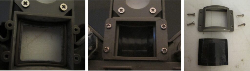
The primary goal of the mechanical system is to provide a window for IR light that doesn’t let moisture through. The optical window is a thin piece of transparent (in the IR spectra) plastic imprinted with a fresnel lens array pattern. The camera housing is rigid (typically injection molded) plastic. A rubber gasket, held in place by a plastic retainer, seals the gap between the plastic housing and the PIR lens.
Inside view of a typical mechanical system for a trail camera (Exodus Lift) PIR sensor. Middle photo shows assembled unit. Left photo shows empty window with sealing rubber O-ring around the perimeter. Right photo shows retaining clip and screws and black Fresnel lense array.
Optical System
The goal of the optical system is to “map” the full field of view onto the two sensor elements in a PIR sensor in such a way that maximizes triggers for animals, but minimizes false triggers. The element which does this “mapping” is a Fresnel lens array. Fresnel lenses are made in flat material by imprinting angled indentations in the lens material (in this case, plastic), which bends the light. By engineering these indentations, many lenses can be inexpensively fabricated on a thin piece of plastic. Importantly, each lens can have a slightly different focal point.
PIR Sensor
Most PIR sensors consist of two infrared-sensitive halves, placed next to each other in a small metal “can”. The sensor detects differences in the rate of infrared light hitting these two sensors. Thus, if one sensor gets “brighter” in the IR, and the other “darker” — the sensor triggers. If both sensors get darker or brighter at the same time, the sensor does not trigger. This “common mode” rejection allows the sensor to detect a moving animal, while ignoring changes is daily temperatures.
Note that the PIR sensor has just two “pixels”. Obviously, two is much less than than the millions of pixels in the primary image sensor. Thus, the PIR detector fundamentally doesn’t see an image — it just sees two pixels. Detecting a small animal moving in any part of the field of view with just two pixels requires some clever optics.
Fresnel Lens Array
The design of the Fresnel lens array is quite subtle, and a source of significant variation between trail camera vendors, and for lenses used in other applications such as home security, lighting control.
For example, in the video below I show the (approximate) pattern from the lens arrays in two trail cameras from our collection The green areas map to one of the two PIR sensor elements, and the red areas to the other. The sensor triggers when the IR intensity from the entire red area changes relative to the IR intensity from the entire green area. The larger the difference, the larger the signal. When the signal exceeds a threshold, the sensor triggers.
The Browning pattern is an example of an “optical wall” between the center of the field of view, and the left and right sides. When an animal crosses this wall, ideally entering the field of view from either side, the IR intensity in the side zones decreases, while the IR intensity in the center zone increases — the ideal case for producing a large signal. A smaller, but still usable, signal results if the IR intensity of the center changes, while the IR intensity in the edges remains the same. E.g. for an animal coming straight towards the camera from the center. I believe this latter mode is what actually detected the bear in clip below.
Fresnel Pattern on Video
The video below shows the approximate image map of lenses from two trail cameras — a Browning Recon Force Advantage (BTC-7A) and Exodus Lift 1. Red portions of these field of views are mapped to one of the PIR sensor elements, and green to the other. The pattern is superimposed on video captured by these cameras to give you an idea of the reasons these cameras might, or might not, correctly trigger for animals. Still, it’s hard to tell just by looking which of these patterns would be most effective, overall, in correctly triggering a camera. See Peter Apps (References) for an in depth view of responses from different camera models.
Video showing PIR patterns superimposed on video for two trail cameras – Browning Recon Force Advantage (BTC-7A) and Exodus Lift2
Electronic System
The PIR sensors convert light to electricity based on the “pyroelectric” effect. The change in temperature of carefully engineered crystals result in a small, transient voltage. The heat from an animal, via infrared radiation, travels from the animal, to the PIR sensor, where it increases the tempearture of pyroelectric crystal a tiny amount, producing a voltage. This voltage is very small (as you might imagine), and must be electrically amplified, filtered (removing noise), and then processed to produce a “trigger” signal which can be read by the camera’s microprocessor. Early PIR sensors used separate, discrete electronic elements for detection, amplification, and filtering. Modern PIR sensors do all of this inside the sensor itself, thus eliminating external parts. This lowers cost, which is good. It also increases reliability, since the very sensitive circuits that process the PIR signal can be prone to moisture damage.
Firmware
Modern PIR sensor must be initialized with proper operating parameters and updated as these parameters change. Thus, newer trail cameras allow for multiple “sensitivity settings.” The firmware is also responsible for waking the camera up when the PIR sensor detects a target.
Integration
All trail cameras integrate these elements together as part of a compact, rugged, and reliable consumer product. Some of the PIR sensors available commercially for DSLRs contain all of these elements (e.g. Cognisys and Camtraptions); some only a subset (e.g. Snapshot Sniper II, and the Game Watcher), which require an external weatherproof housing.
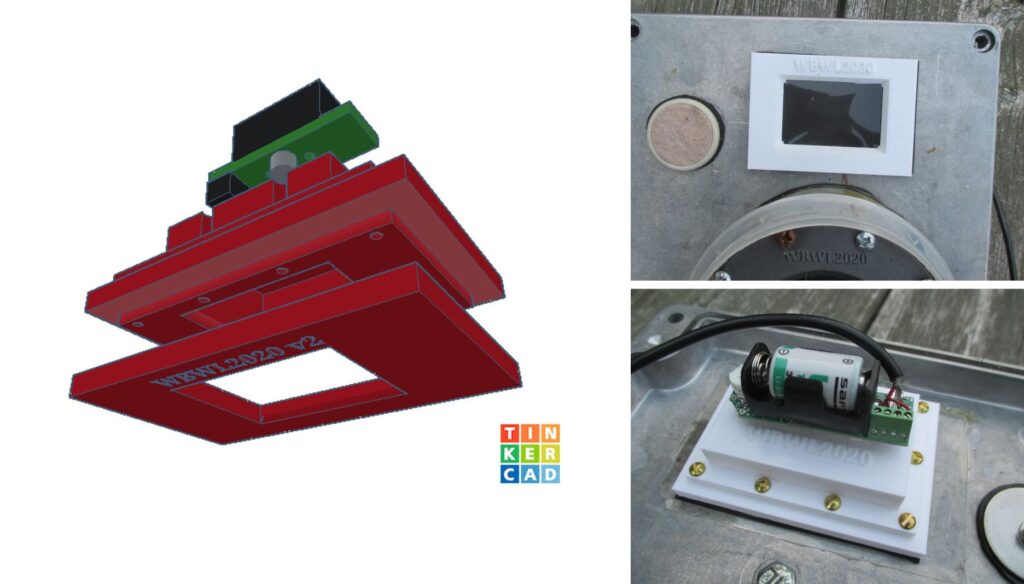
Below is an example integration using the Snapshot Sniper II detector module (green and black in CAD photo below). Although this sensor performed better in the field vs. the original Snapshot Sniper II configuration, we found that it was still not as good as the sensor in our Browning trail cameras. That is, co-located, our sensor missed more animals that were captured by the Browning.
3D model (left) and photos (right) of finished PIR detector housing I made for Snapshot Sniper II sensor module (center, with battery). This design includes a rubber gasket (not shown in CAD diagram) , and does a better job at keeping moisture out vs. the Fresnel lens array included with the SSII. I used a WA0.9GIT1-JB Poly IR4-0.015 Fresnel lens array from Fresnel Technologies, Inc. For all this work, this detector still misses triggers which are caught by a Browning Recon Force Advantage that we co-locate with our DSLR camera traps in the field.
Fresnel Lens in Wikipedia: Originally developed by French physicist Agustine-Jean Fresnel in 1821 in response to need for lenses in light-houses.
Comments
Deep Tech: Trail Camera PIR Sensors — 6 Comments
Excellent article.
I addition to all that, some makes and models have the active detection confined to a horizontal strip across the field of view. Reconyx shows theirs in their user manuals, I now discover that Browning Patriots and ProXDs do the same, but keep quiet about it. It makes a huge difference to the optimum set-up for captures.
Thanks! I was surprised by the variation in the “zoning structure” (implemented by the Fresnel Lens array) between different camera vendors. I started to put together a simulation framework that would allow me to evaluate these detection zone schemes virtually. I planned to validate this model with the real world setup you describe in “Are camera traps fit for purpose? …” Eventually, my idea was to use the validated model to create an “optimal” Fresnel lens zoning architecture. Alas, other projects have intervened. If you know of anyone else out there with time or interest in pursuing this topic, I would be happy to share my thoughts and work to date.
Thanks Peter.
I typically need to set my trail cameras in bush settings. On windy days I pay the price with many false triggers.
Your thoughts please on masking the upper half of the PIR sensor to try and prevent bush above waist height causing false triggers.
I am only trying to monitor deer so I do not see it necessary to detect movement in the upper half of the field sensor zone.
This may already be done by your trail camera. See: Deep Tech: Trail Camera Detection Zones It’s probably worth measuring the detection zones for the camera you are using. Based on the models I’ve measured, there are several possibilities: 1. the detection zones may already below the center line of the image FOV; 2. The detection zones may only be above the image centerline, so blocking the top half of the Fresnel lens array may prevent the camera from triggering at all; 3: The detection zones may be smack in the middle of the frame, in which case you may be able to block out the top half of the detection zones, possibly with some loss of detection sensitivity.
You may have already read my post Avoiding False Triggers in Trail Cameras. One idea (if it’s supported by your camera) is to limit the operating hours to avoid times of day when false triggers are most likely (typically during the hottest, windiest portions of the day). Of course, this may also filter out your target species.
Unfortunately, Tasco doesn’t seem to offer PIR lens replacements online. One option would be to find a “parts camera” of the same model online, and harvest the PIR lens from that.

Excellent article.
I addition to all that, some makes and models have the active detection confined to a horizontal strip across the field of view. Reconyx shows theirs in their user manuals, I now discover that Browning Patriots and ProXDs do the same, but keep quiet about it. It makes a huge difference to the optimum set-up for captures.
Thanks! I was surprised by the variation in the “zoning structure” (implemented by the Fresnel Lens array) between different camera vendors. I started to put together a simulation framework that would allow me to evaluate these detection zone schemes virtually. I planned to validate this model with the real world setup you describe in “Are camera traps fit for purpose? …” Eventually, my idea was to use the validated model to create an “optimal” Fresnel lens zoning architecture. Alas, other projects have intervened. If you know of anyone else out there with time or interest in pursuing this topic, I would be happy to share my thoughts and work to date.
Thanks Peter.
I typically need to set my trail cameras in bush settings. On windy days I pay the price with many false triggers.
Your thoughts please on masking the upper half of the PIR sensor to try and prevent bush above waist height causing false triggers.
I am only trying to monitor deer so I do not see it necessary to detect movement in the upper half of the field sensor zone.
This may already be done by your trail camera. See: Deep Tech: Trail Camera Detection Zones It’s probably worth measuring the detection zones for the camera you are using. Based on the models I’ve measured, there are several possibilities: 1. the detection zones may already below the center line of the image FOV; 2. The detection zones may only be above the image centerline, so blocking the top half of the Fresnel lens array may prevent the camera from triggering at all; 3: The detection zones may be smack in the middle of the frame, in which case you may be able to block out the top half of the detection zones, possibly with some loss of detection sensitivity.
You may have already read my post Avoiding False Triggers in Trail Cameras. One idea (if it’s supported by your camera) is to limit the operating hours to avoid times of day when false triggers are most likely (typically during the hottest, windiest portions of the day). Of course, this may also filter out your target species.
What will fit a Tasco camera? Wood peckers ruined the lens.
Unfortunately, Tasco doesn’t seem to offer PIR lens replacements online. One option would be to find a “parts camera” of the same model online, and harvest the PIR lens from that.