This page gives “how to” instructions for converting a Browning Recon Force Advantage (BTC-7A) Trail camera to White Flash. See: IR to White Flash Trail Camera Conversion for background and context. I have also recently added a video at the end of the post showing the whole process.
I am indebted to Dan Potter, who used early versions of these instructions to convert some of his cameras. I have incorporated photos from Dan’s build, along with his suggestions for improvement into the current post. If you find any areas in the instructions below which are still unclear, please note them in the comments and I will do my best to fix.
Disclaimers
- Following these instructions worked for me, but I provide no guarantee it will work for you:) I will do my best to answer questions posed in comments below.
- Note that physically modifying your trail camera and/or installing non-factory firmware may void your warranty with the manufacturer. Continue on with this project at your own risk.
- I provide no guarantee or endorsement of suppliers listed on this page, although I have successfully used several of them with no problem.
Before You Start
To complete this project, you should:
- be proficient with a soldering iron and through-hole PCB assembly. If not, there are lots of tutorials online
- have a PCB soldering setup
- have a pair of small diagonal cutters for trimming excess leads from LED after they have been soldered
- have a 3 mm Phillips head screw driver (for disassembling trail camera and removing PCBs inside the camera
- have a dental tool, or some other thin hooked piece of metal to remove the rubber “fillers” in the screw holes of the camera case
Acquiring Parts
Below are spots on the web to acquire parts. If folks find better or less expensive suppliers, feel free to mention in a comment and I will do my best to add to this post.
Printed Circuit Board
The PCB is provided as an open source hardware project hosted on a couple of platforms. Following one of links below will get you to the project page. Per board cost can be much less than shipping. If you order more than you need, consider making available to friends.
- pcbway.com LED PCB for Conversion of IR Trail Camera to White Flash
- oshpark.com LED PCB for Conversion of IR Trail Camera to White Flash
White LEDs
I have used LEDs with the following spec. The color frequency is important, I think, as these seem to produce the most color-accurate images with the Browning auto-white-balance algorithm. The viewing angle is also very important. I have tried more readily available LEDs with a narrower field of view (e.g. 25 degrees), and found that it results in a “bright spot” at the center of the image, with dark areas around the periphery. The 45 degree LEDs provide more uniform illumination.
5 mm White LED
Model: WC451-21 – White
Color Frequency: 6000K-6500K (White)
Luminous Intensity: 41,000mcd
Viewing Angle: 45°
Forward Voltage: 2.7v – 2.9v
Typical Voltage: 2.8v
Typical Forward Current: 20mA
Style: Round 5mm – T1 3/4
At the time of this writing, these are available at PCBOARD.CA, Model: WC451-21 – White
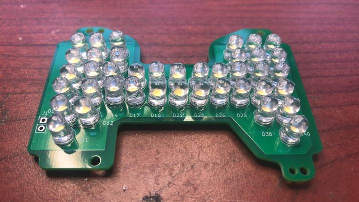
The design requires 40 of these LEDs per board.
Assembly
PC Board
This board is relativley simple – there is only one part type — the white LEDs. But there are a lot of them, packed together.
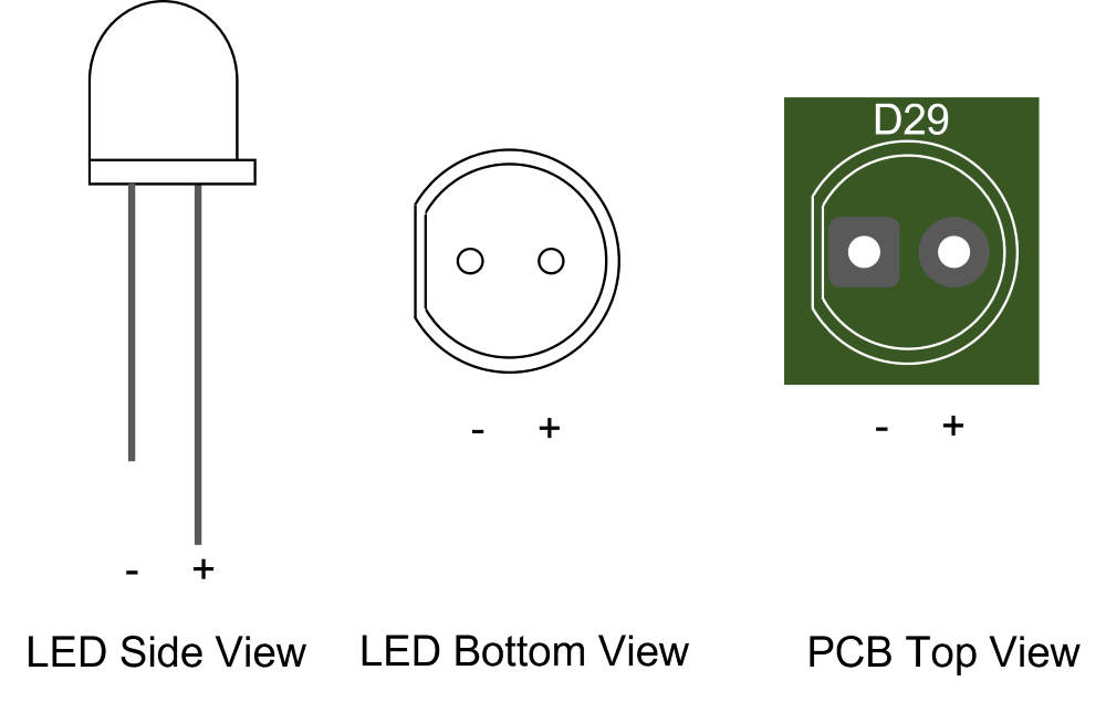
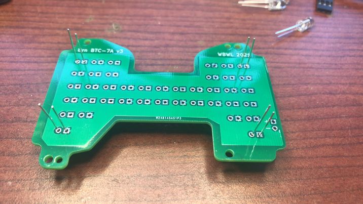
In installing these LEDs in the PCB the polarity matters! The anode (positive) terminal is the longer of the two leads; and is on the side of the LED that is rounded. The cathode (negative) terminal is the shorter lead, and on the side of the LED with a flat edge. The PCB silkscreen shows the flat/short/negative side of the LED (cathode) ; and the solder pad is square. See diagram below
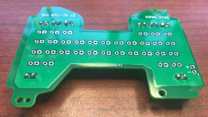
Per Dan Potter’s suggestion, start PCB board assembly by placing 4 LEDs on each of the 4 corners of the board, as shown below. Before soldering anything, double check that you have the polarity right! The LEDs leads should all face in the same direction, with the short lead of each on the right side.
Testing the board isn’t necessary, but can be a good idea. You can use a current-limited power supply set to as much as 400 mA. The voltage required to get to this current will be approximately 6-7 Volts. You should see light from all the LEDs well below this current. You can also use the 12V battery pack from the camera to drive the LED board if you put a ~15 Ohm, 5W resistor in series with the LED panel to limit current. Don’t leave out the resistor, or you could burn out your LED array!
Camera Disassembly and Reassembly
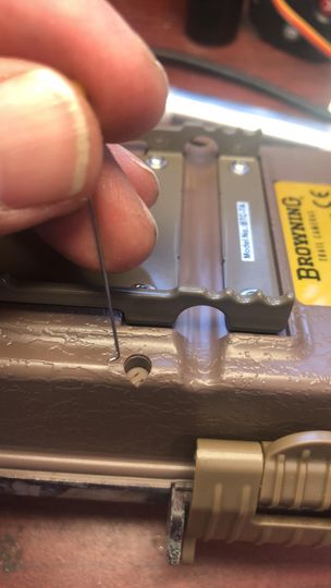
Remove the 6 rubber “stoppers” sunk into the screw channels. I use a hooked dental tool for this, but you can also fashion a make-due tool by putting a small bend at the end of a sewing pin.
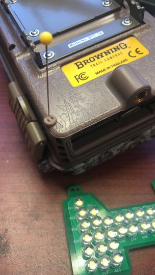
Remove 6 phillips head screws that hold the back case on.
Remove 6 phillips head screws that hold the primary circuit board in. Carefully pull out the main PCB, exposing the LED PCB. There are several wires and cables from the main PCB, but you should be able to access the LED PCB without removing any of them. Be patient.
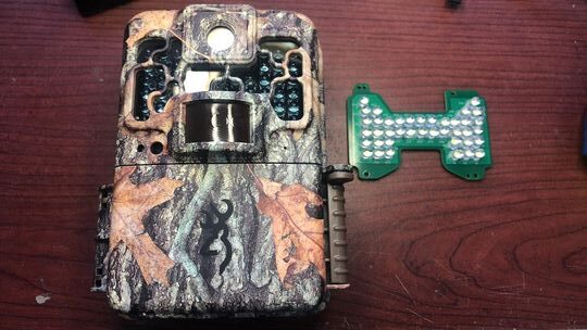
Remove the existing LED board from the camera by removing the 4 small Phillips head screws that fasten it to the front plate. Once out, unsolder the two wires (black and red) from the old flash PCB. Tack these wires onto the new board, red to the pin marked “+” and black to the pin marked “-“.
Install the new board, by re-installing 4 mounting screws.
Reverse earlier steps to reassemble camera.
Installing New Firmware
The link below contains a copy of the factory default firmware, and the new “white flash” firmware.
This repository contains a number of firmware images with various features as well as the factory default “Baseline” image. Look for images with “White Flash” enabled. The default, standalone white flash conversion image is in the directory WF_E_CR_NV. See “README.md” file at the site for a full description of other white flash capable images with other functions.
Download Instructions
- Find the copy of brnbtc70.BRN file you’re interested in the appropriate folder in the repository. Click on it; then select “Download”
- Copy the downloaded file onto an SD card at the “top level” (not into a folder on SD card). You can do this without physically swapping SD card around by plugging the BTC-7A into a USB port on your computer, and copying the brnbtc70.BRN file into the folder which appears with the camera
- Note — the file must be named “brnbtc70.BRN”. Sometimes downloading from your browser will add extra characters to distinguish it from previous downloads — e.g. “brnbtc70(1).BRN”. If this happens, rename file to “brnbtc70.BRN” on the SD card.
Firmware Installation
Before installing new firmwarwe, make sure you have batteries that will easily power the camera for the several minutes it takes for the firmware upgrade. Losing power during firmware upgrade is bad, requiring that it be reprogrammed by the manufacturer.
On the BTC-7A Camera with a firmware update SD card installed:
- Press “Mode” button
- Select “CAMERA SETUP”
- Select “FW UPGRADE”
- Select “YES”
Display should show “UPGRADING” for about 2-3 minutes; DO NOT TURN OFF OR REMOVE BATTERIES DURING THIS TIME! (this will “brick” the camera). Camera will then “Reboot” with new firmware.
Note that firmware update will reset all camera configuration and settings, including date and time.
You can tell that firmware update is successful if you see a new picture in place of the vendor “splash” screen:.
Test your camera in a dark room, or by covering the light sensor to the left of the PIR sensors. You should see the white flash come on when it is taking video or photos.
Restoring Camera to Original Configuration
If, for whatever reason, you want to put the camera back into it’s factory configuration, follow these steps:
- Re-install the IR flash board removed earlier
- Follow steps above for firmware update, but with an SD card containing a copy of the factory default firmware.
Troubleshooting
| Problem | Action |
| No LEDs light | Make sure that you installed the black and red wires correctly. Black to “-” and red to “+”. It is possible that all the LEDs are in backward (yes, I’ve done this). In this case, you can fix by reversing black and red wires. |
| Some LEDs won’t light | LEDs are in groups of 2. If you see a set of 2 that’s not coming on, chances one or more of this group is in backwards. Use a diode checker to find the culprit. Unsolder the backwards part(s), flip it around, and resolder. Alternatively, remove them both, and install new ones, with proper polarity |
| Firmware update menu will not highlight “Yes” as an option | Check to see if the name of the firmware file has been changed during download. The file must be named “brnbtc70.BRN” to be “seen” by the camera. Sometimes downloading from your browser will add extra characters to distinguish it from previous downloads — e.g. “brnbtc70(1).BRN”. If this happens, rename file to “brnbtc70.BRN” on the SD card. |
:
:
:
Hi Bob,
This white LED conversion was my 1st time soldering and I watched several different You Tube videos to learn the proper technique before I attempted this project.
Attempt 1 went well, LED lit up when resoldered to power, but LED’S were wiggly as they had gaps between them and PCB board. But still worked, if not all pointing forward in a uniform fashion.
After gaining confidence on board one, I attempted a second board. Attempt 2 got LED’s tight to board (bent legs w/ tweezers while pulling up) but I soldered the whole board before I realized I was working on the wrong side! There is a lot of flipping of the board involved but this taught me to close down distractions while doing project. There was no board 3.
I found placing LED’s on the 4 corners an excellent idea to start.
Then, on board #2, I placed LED’s in every other hole across whole board, bent legs to hold LED’s tight to board, soldered legs in a progressive sequence across board, and cut off excess legs as I went.
I then went back and placed LED’s in holes I had skipped. I felt this gave me more room to work, but your preference may be different.
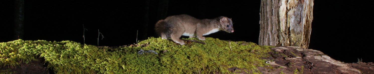
Overall the project was very doable and yielded amazing results. When the lights come on at night it is surprisingly bright. Having never worked with white external light I found the brightness to be more than I could have anticipated. It will be interesting to see color pictures surrounded by a rim of night darkness!
Thank you Bob for all the work you did to make this possible!
Congratulations! Glad this worked for you. Bending the leads to help snug the LEDs to the board works. Having done several of these now, I built a little jig out of some coat hanger wire and some weights that applies constant pressure down on solder side of the PC to hold the LEDs flush. I found that a slightly compliant work surface (e.g. a mouse pad) helps the “even” out slight differences in LED height. Finally, doing those 40 LEDs as a number of smaller groups, as you discovered, also helps. Hope you get lots of great color night shots with your upgraded camera.
Dan Potter’s photos really help visualize the LED array—I was wondering how the white flash would look compared to the stock IR. Glad you added the video too, since the step-by-step is always easier to follow with a demo.
Glad you found this “stone soup” post useful!
I’ve been looking for a clear guide on converting the Browning BTC-7A to white flash, so the video you added at the end is going to be super helpful before I start dismantling mine. It’s really cool that Dan Potter shared his build photos and tips to help refine these instructions. I’m definitely going to give this DIY conversion a shot this weekend.
Alright! I have a small, but dedicated following for this post. Let us know how you make out, or if you run into any issues.
It’s awesome that you added a video showing the entire conversion process for the BTC-7A, as visual guides make these DIY projects way easier to follow. Huge props to Dan Potter as well for testing the early instructions and sharing his build photos. I’ve been wanting to convert my Recon Force to a white flash, so this updated guide is exactly what I need to get started.
Glad you found it useful. Let us know if you give it a try.
I DID IT!!!! I AM STOKED!!! I am a 64 year old woman and this project was super simple for a former PCB board assembler. Your instructions were detailed and simple for anyone to follow. When I updated the firmware and that splash screen popped up I was certain it was a success!! Tested it out and all LEDS are firing!! Can’t wait to try it in the field. Bob, I can’t thank you enough for all of your help. I appreciate you sharing this hack with everyone. I really wish there were more options for white flash cameras out there, but converting my favorite camera, the Recon Force Advantage, to white flash has me over the moon with excitement!!! Thanks at least a million!!!
So glad to hear! As someone who enjoyed putting together Heathkit PCBs in my youth, I confess to an interest in enabling more electronic hacking. Good luck with your “new” white flash camera!
Update — I’d like to extend this post with examples from folks who have made the conversion. Please PM me if there are any photos or videos you’d like to contribute (with whatever attribution you prefer, of course).
Hello
Great project!
What do you think of tweaking the light sensor signal so that the camera thinks its always day?
Then it would not be necessary to alter the firmware.
Regards Daniel
7x Foscam C2 (Wifi) as Nestcams
2x Suntek HC-900 Pro (Celluar) as Beaver Cams
Thanks! I considered a number of hacks short of changing the firmware. The light sensor is a photo-diode, I believe, and am not sure whether shorting it out or removing it results in camera thinking “always daylight”. The bigger problem is that if existing firmware thinks it’s daylight, it doesn’t turn on the flash 🙁 And we definitely need that. And there’s all sorts of other trouble I can get into 🙂 now that I can patch the firmware. See, for example (if you haven’t already): Using Trail Camera to Trigger a DSLR Camera]
Hi Bob
Just get a new HC-940 direct from suntek one week ago.
Good price, free cloud and lithium cells. Its now placed on a small creek in our city to look for beevers.
Already opened it to look inside.
I will change the lens, already ordered a set on aliexpress.
What do you think of launching an project for an open source trailcam?
Regards Daniel
Hi, Dan.
Interested to hear how you make out with the HC-940.
I am working on a “Lens Hacking” post right now — also awaiting lenses. It was a bit tricky finding ones that actually fit in the tight space between the PCB and the waterproof “window” in the front case. I found a 5.8 mm, low distortion, TTL = 10mm, M12 lens (no IR) from Towin (HFOV ~55 degrees — slightly wider than the stock 43 FOV (~7mm?) lens reported for the Browning cameras I’m working on. I found another, much wider-angle lens from Commonlands (2.1 mm) but am afraid the TTL (15mm) is a mm too long 🙁 I lost patience with Alibaba — no way to search parametrically. Sounds like you persevered. What lens did you end up going with?
The question of open source camera project is complicated, though interesting. Will contact you via email to discuss.
Just come across your website, very cool work. I’ve done some hacking with spypoint cameras
Can I ask what you used to reverse engineer the firmware?
Thanks! Glad you found us.
I used Ghidra (https://ghidra-sre.org/). Or, should I say, I used about 1/10 of Ghidra. “The Ghidra Book” does a pretty good job of taking a Ghidra-newb from “zero” to “productive”.
I also used a 3.3V TTY USB adapter and PuTTY to tap into the on-board debug port on the Browning trail cameras (I’m not sure if other cameras have such ports, or, if like Browning, they keep this port turned on in production cameras)
And, finally, I used RevelProg IS to read and reprogram the onboard EEPROM chip which stores the code and filesystem. With the right design, you can do this in-situ with an SOIC clip, but on the Browning’s, at least, I had to remove the EEPROM to read and reprogam it. I used an SOIC SMT to ZIFF header from http://www.Aprilog.com to make removing the EEPROM much easier. Once you’ve figured out the firmware loader, you don’t need mess with the EEPROM anymore, in principle. In practice, it’s very each to write new code which bricks the system. There’s probably a way to reprogram the EEPROM in situ (e.g. for manufacturing), but I couldn’t figure that out.
To insert new code, I used the GNU c compiler, linker, and loader, and some custom python code to package up the final firmware image.
If you want more detail, let me know. Happy to provide directly over email.
Hey Bob – the posts and work you’re doing are fascinating, thank you. I wondered if the firmware could be changed to allow the videos to record longer than 20 seconds at night? I know this is a limitation put on by the factory to prevent the IR array overheating, but I always wondered if it was too precautionary as the camera can retrigger anyway in less than a second.
Thanks!
Regarding the night-time limit of 20 seconds on the BTC-7A (and other) cameras. I have found that these cameras have no problem keeping the IR LEDs on indefinitely. As you say, they need to do this to handle the “consecutive triggering” case. Thus, the 20 second limit on night time video seems more aimed at conserving battery charge.
All of the firmware for the BTC-7A I’ve modified so far (e.g. for White Flash, and to enable use as a DSLR trigger) bypasses this limit — so it’s definitely possible! Based on your comment, I’ll work on an version of the firmware that contains only the video limit bypass, and mods to the playback screen which show the date/time for photos and videos in a readable font which we’ve found useful in reviewing images in the field. Thanks for the suggestion, and stay tuned…
PS: I hope your target is for the BTC-7A — as it’s (currently) the only model my firmware hacks support.
OK — I just posted a new firmware image, “CR_NV” (Custom Ribbon, Night Video limit) to my GitHub site for BTC-7A firmware images. Look for “CR_NV” image and follow instructions at: https://github.com/robertzak133/BTC-7A-Firmware-Images/blob/main/README.md
With this firmware image, your camera should take the set video length day or night. Keep in mind that night video consumes batteries at 2-3x the rate of daytime video.
Note that none of these images are approved, supported, or even acknowledged by Browning. Loading them on your camera may void any remaining warranty you may have. I test them all before posting, but I cannot offer any guarantee that they’re work for you. The github site also contains a “BASELINE” firmware image which will take the camera back to the factory firmware.
If you use this image, let me know how you like it.
Hey Bob, I’m so sorry I missed these replies! This is amazing, been after this for years – going to test this out shortly!
James
Glad you found us eventually. Looking forward to finding out how this works for you.
Hi Bob,
I have completed several boards and I have been testing one conversion in the field for several months. I have been studying the Humboldt’s Flying Squirrels with your white flash conversion and I couldn’t be happier with the results. In attracting the Humboldt’s to a feeder, I have also attracted the attention of the local raccoon and black bear populations. The camera will frequently operate near continuously every night over multiple nights without fault. I have enjoyed adding this approach of white light to my available options.
Is it possible your CR_NV firmware would operate on the BTC-8A?
I have read all of your contributions and really appreciate all of your hard work.
Thank you, Dennis
That’s great! I’m glad the conversion has worked for you. The Humboldt’s work sounds very exciting.
Regarding the BTC-8A (Spec Ops) version of the Advantage family. I believe that in, in principle, the 8A will run the 7A firmware. You would lose the barometer in the info strip (which is not supported in the 7A). There may be other subtle differences. I have done this in the past, but never studied the firmware differences systematically. There are two relatively small changes that would need to be made to the firmware image. Each of these could be done pretty simply. Here’s the rub: I don’t have a recoverable BTC-8A to test this on. My experience with firmware (and software in general) is that it doesn’t work unless it’s tested 🙁 It is unlikely, but in the worst case, it could “brick” the camera. If you are willing to risk it, let me know in a reply.
As you will have noticed, I have not ported the WF conversion to the Elite HP5. Several reasons: the LEDs are more specialized; the PCB outline is more complex; and Janet and I have enough WF cameras for the time being 🙂 ; other priorities. Still, if there’s enough interest out there, I may do this in the future.
Bob,
I really appreciate your time and effort. I am needing clarification on polarity. Your description is consistent with the leds and board I received. I am however confused as to why it appears the led polarity is marked the opposite of the power connection polarity by your description? The connections for the led positive is a circle, however the power connection positive is a square? I am enjoying reading all of your contributions to the site and again I appreciate your time and efforts. Thank you Dennis
Oops. Disregard the “square pad” on the connection to the power supply — my design is apparently inconsistent on this point. Follow instead the “+” and “-” labels for the power supply connection on the backside of the board: “+” to red, “-” to black. (if you somehow have an earlier version of the PCB without these markings, let me know)
Let me know how you make out!