Deep Tech: Trail Camera Detection Zones
Knowing the detection zone pattern can help produce more “true triggers” and fewer “false triggers.” In an earlier post Deep Tech: Trail Camera PIR Sensors I covered some of the details of PIR sensors. Based on feedback from subscribers, though, I realized that I had missed some subtle aspects of the Fresnel lens optics and detection zones for PIR sensors. In this post, I look more closely at trail camera detection zones, and how they work. I also give two straightforward ways to find the detection zones in most cameras. I use these method to measure the detection zones for four camera models.
What is a Trail Camera Detection Zone?
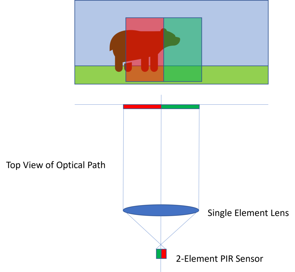
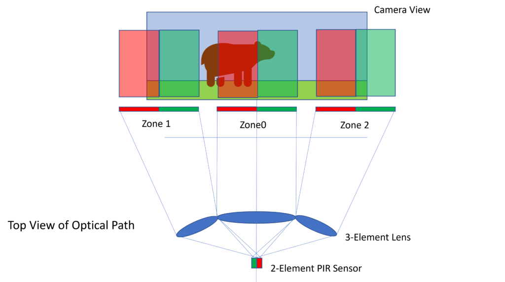
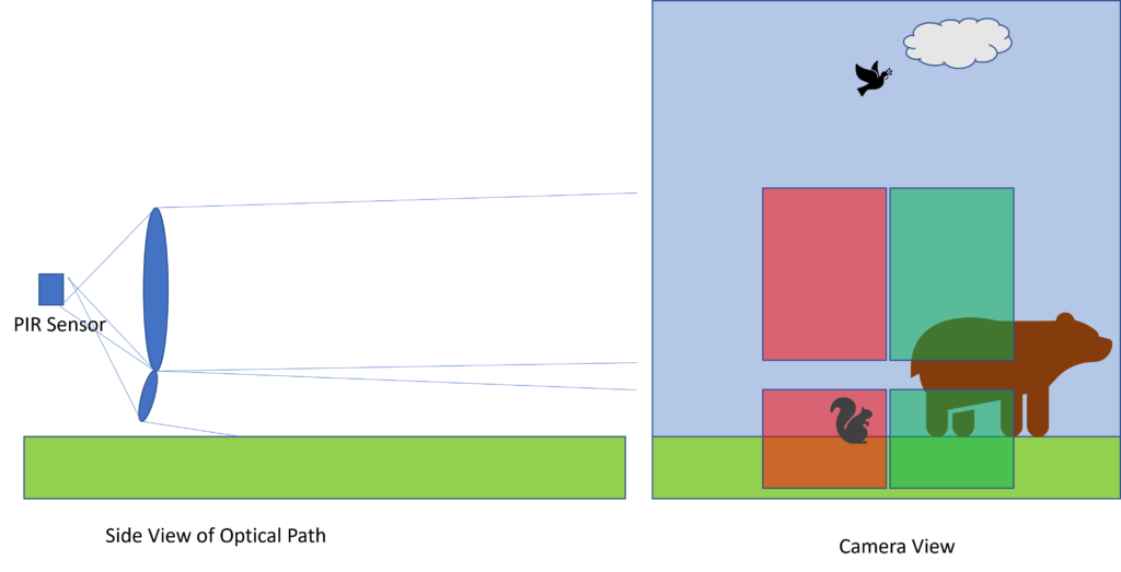
From a practical perspective, a “detection zone” is a region in front of the camera in which moving heat will trigger the PIR sensor. From an operating perspective, each detection zone is the result of a lens element focusing a portion of the scene onto two detector halves of the PIR sensor. The camera triggers when a differential change in heat between sensor halves exceeds a detection threshold.
The diagrams below shows the how this works: for the simplest, one zone lens setup; for a multi lens setup that creates multiple horizontal detection zones; and for a multi-lens setup the uses two lenses to create multiple vertical zones.
Measuring Trail Camera Detection Zones
In Deep Tech: Trail Camera PIR Sensors, I presented presumed detection zone patterns for two camera model. I arrived at these drawings by visually inspecting the Fresnel lens array on each camera. As shown in the photo below looking out of the Fresnel lens on a Browning camera, the 3 lens elements are clearly visible.
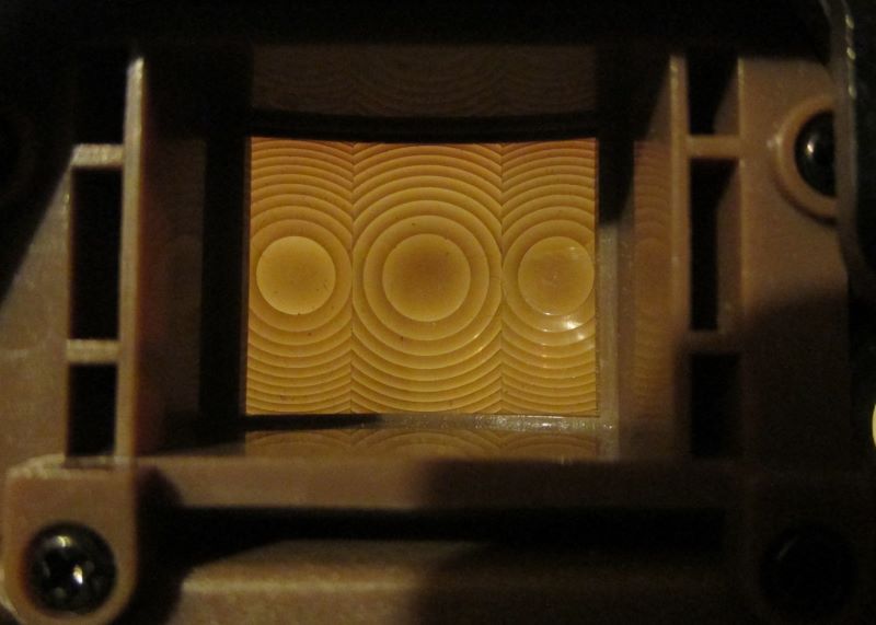
I then superimposed these patterns onto a few trail camera images. Unfortunately, this mapping was just an assumption in my part. In reality, the different zones could be separated from each other, or may include more or less of the horizon or foreground, depending on the specific optics of the Fresnel lens array. Is there are way to easily tell exactly how a given Fresnel lens array maps onto the scene captured by the camera?
The answer is yes! Here are two methods that you can use with any camera. The first one is easier to set up for a single measurement, and relies an “aim test” mode of the camera. The second method is more involved, but works with any trail camera. Thanks to subscribed PeterA for suggesting the outline of the second mehod which I expand upon here.
The basic idea is to move a small heat source around against a screen in front of the camera. In the first method, when the test LED comes on, a mark is made on a screen. This process is repeated multiple times, gradually producing clusters of marks where the detection zones are. In the second method, the camera is set to take photo, and the heat source is slowly scanned in front of the camera. the location of the heat source in the resulting photos (which occur only when there were triggers) are used to create detection zone cluster. Here are the details
Method 1: Using the “Aim Test LED”
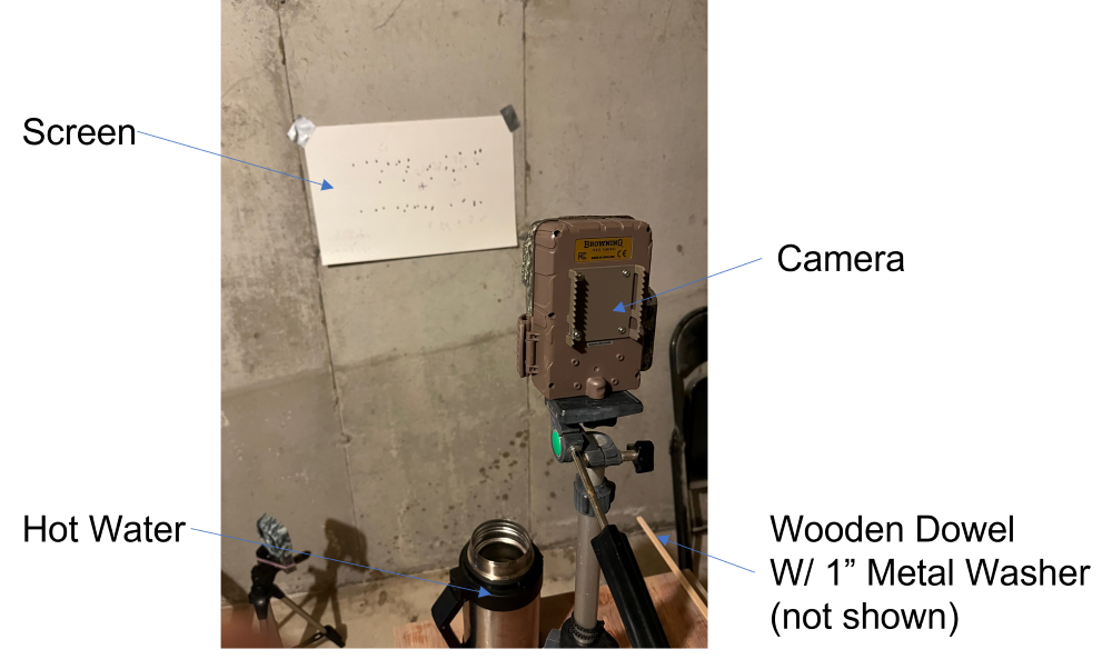
The setup is featured in the photo below. It includes:
- Trail Camera Under Test: I mounted the camera up on a tripod, facing a wall.
- Writable Screen: I taped a sheet of poster-board onto the wall, roughly in the center of the camera’s field of view. The camera should be close enough so that it’s entire field of view is about half of the paper area. This allows marks to be made on the paper outside of the camera’s field of view.
- Movable Thermal Target: For a thermal target, I used a large metal washer (approximately 1″ in diameter). Placing a marker tip through the hole in the center of the washer is a convenient way to mark the position of the washer. I attached the washer to the end of thin wooden dowel with a screw through a second small hole I drilled in the washer. You can use other material, but it should be a thermal insulator. Not metal. Dowel should be long enough so it can be held, and used to move the target around, without your warm hands getting into the field of view — about 3 feet. To create a “warm” target, I dipped the metal washer into very hot water every few minutes..
Locating the Camera Image
I started by putting the camera in preview mode. Looking at the LCD, I found the positions on the camera’s preview screen corresponding to the corners of the image. I marked these on the poster board. This allowed me to locate the detection zones relative to the camera’s field of view.
If your camera doesn’t have a preview screen, you can achieve the same effect. Draw some reference marks on the screen. Next, take a picture of the screen with the photo. Then, use the photo to figure, and reference marks, to figure out the approximate field of view of the camera.
Creating a Thermal Target
Every few minutes, I dipped the washer at the end of a thin wooden dowel into some very hot water. The washer just needs to be warmer than the temperature of the wall. There is no need to control its precise temperature.
Structured Dither
I held the thin dowel by end opposite the washer. This kept my warm hands out of the field of view of the sensor.
I moved the target side to side against the poster board taped to the wall, scanning across the horizontal field of view. I did this somewhat slowly, to compensate for any delay in the detection circuit.
When the “aim LED” came on, I marked a spot on the poster board. Around this spot, I then dithered the target back and forth horizontally. I marked a spot where the LED came on again.
Example of Raw Data
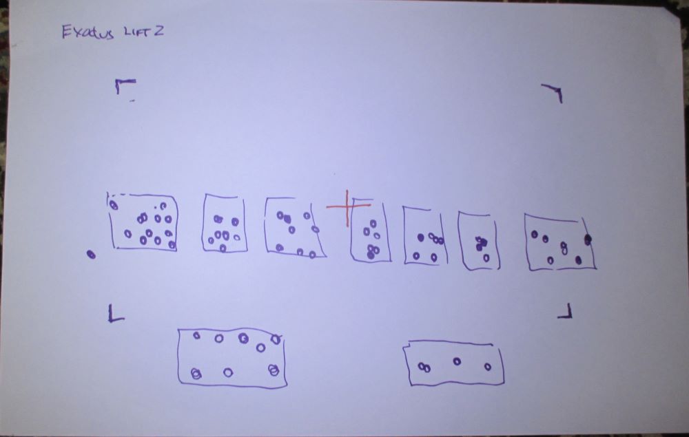
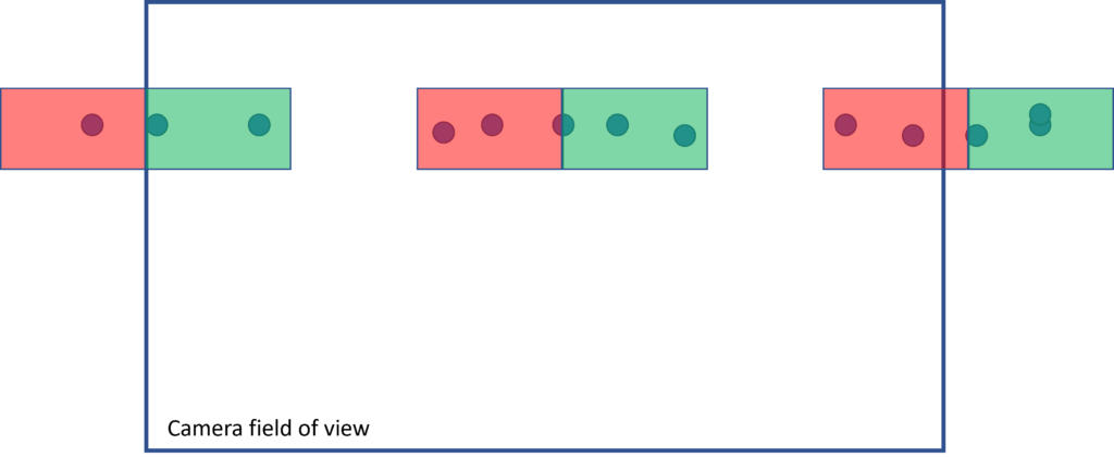
The photo below shows the poster board after I measured the detection zones on the Exodus camera. Although the resolution is limited by the size of the washer I used (about 1″ in diameter), clusters of dots representing the target position when the “aim LED” illuminated clearly show discrete detection zones. Note that movement of the target outside of these zones never resulted in a detection.
Method 2: Using Trail Camera Photo Captures
After publication of my original post, subscriber PeterA suggested a variation on the method above. Basically, to use the trail camera’s own image sensor to capture the position of the small heat target when the camera triggers. This method has the advantage of not requiring the “Aim Test” feature, and thus working with any trail camera. Also, no magic markers.
There are a couple of challenges. For one, several cameras I’ve looked at have detection zones which are out of the field of view of the image sensor. Also, since there is no realtime feedback (as there is with the “Aim Test”), the procedure requires more patience. Since it takes longer, I also opted for a solution for an electrically driven heat target to avoid the use of hot water.
Heat Source
I attached a 10 Ohm, 5 Watt ceramic resitor to my target washer. See photo below. I used a backing piece of thin aluminum to clamp the square resistor into place, and in close thermal contact with the washer.
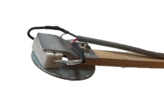
This assembly was at the end of by 3′ dowel. I ran a two-wire cable up along the dowel and attached one wire to each of the two resiter leads. I used some nylon cable ties to hold the wire to the dowel. I made the cable long enough so that I could connect it to a power supply, and still be able to move it around easily.
Not Too Hot!
I found that it took a little adjusting to get the right amount of heat out of the resistor. At the full 5W rating of the resistor, it was well above 150F, and very hot to the touch. Worse, it tended to heat the dowel, and I suspect the target, leading to extraneous sources of changing heat, which confused the experiment. In particular, I found that the camera was triggering with the washer almost anywhere in the field.
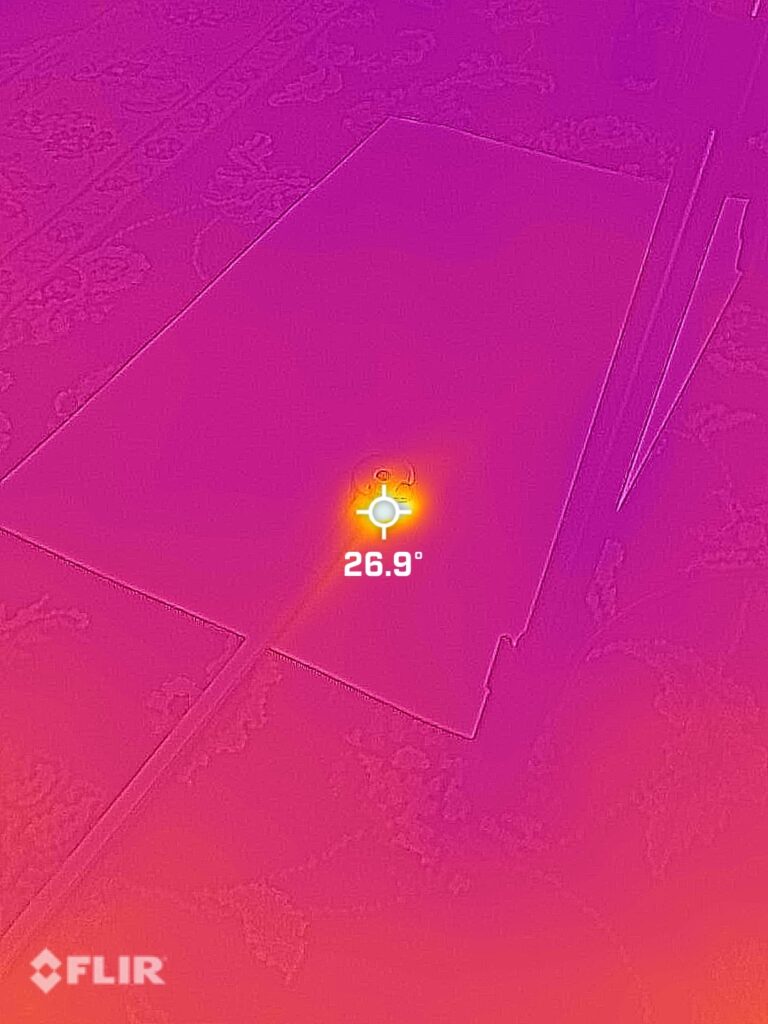
Instead, I set the voltage at 2.8 Volts, which drew 0.28 amps, or 0.78 Watts. This was enough to heat the washer up to 26.9C (80.4 F) — which was easily detectable by the PIR sensor. At the same time, it was not hot so hot that too much heat “leaked out” around the target. See thermal iamge below.
Setup
I set the camera up on a tripod, looking down at the floor at a height of about 25 inches (64 cm). I ajusted one leg of the tripod to get the other two as close to vertical as I could without the whole thing tipping over then tilted the camera up a little from vertical to make sure the tripod legs were not in the photos.
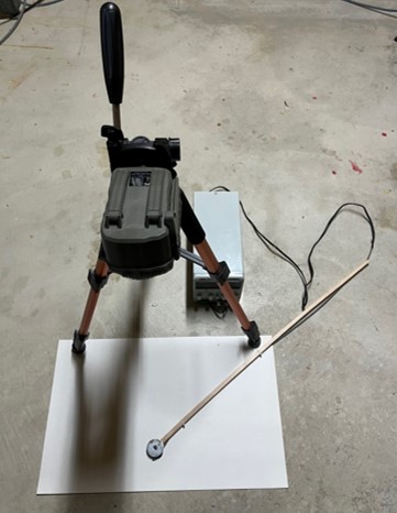
I set the camera to take a single photo per trigger, and on a minimum retrigger time (for the STC DS4K — 3 seconds)
I turned on the power supply and let the heated washer reach equilibrium (about 10 minutes).
Manual Raster
Now for the tedious part. I used the long dowel to “scan” the heated washer “raster” style over a poster-board target on the floor in front of the camera. I moved the washer one washer diameter at a time, then stopped and waited 3 seconds (for the camera to re-arm, if necessary), before moving it again. I included in the scans areas to the left and right of the camera field of view to capture any detection zones outside the camera’s field of view.
Post Processing In PowerPoint
After scanning the whole target area, I turned off the camera and removed the SD card. I loaded all of the photos taken into a blank slide in PowerPoint, which conveniently put them all one on top of each other over the full frame of the slide. I pasted a PowerPoint circle over the center of the washer where ever it was in the photo, then I deleted the photo from the slide, which exposed the next photo. Sometimes I had to go “off slide” to place the dot.
Where the washer was out of the photograph, I used markings on the dowel (which appeared in the photos) to extrapolate the likely position of the heated washer target.
I did the same until there were no more photos. This left me with clusters of blue dots on a blank slide. I grouped these into clusters, made a rectangular outline the size of the slide, grouped everything together, then shrunk the resulting combined shape proportionately until everything fit within the bounds of the slide.
Updated Detection Zones for Browning, Exodus, Bushnell, and Stealthcam
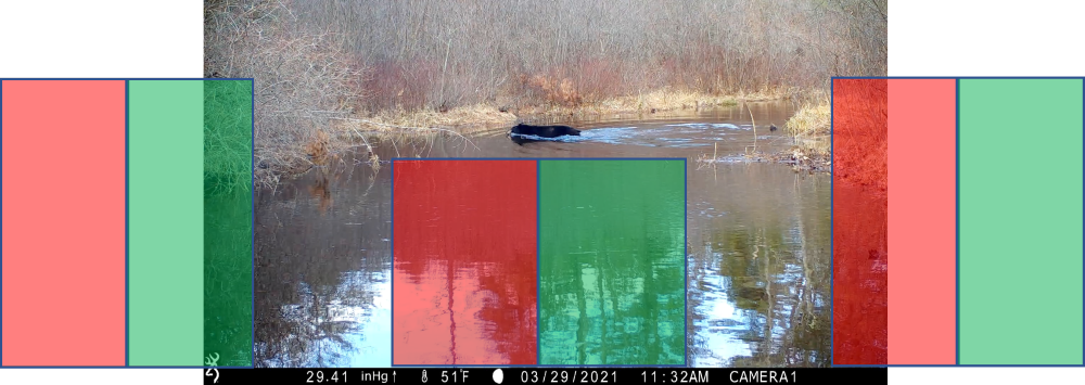
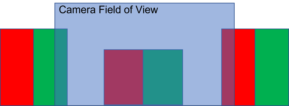
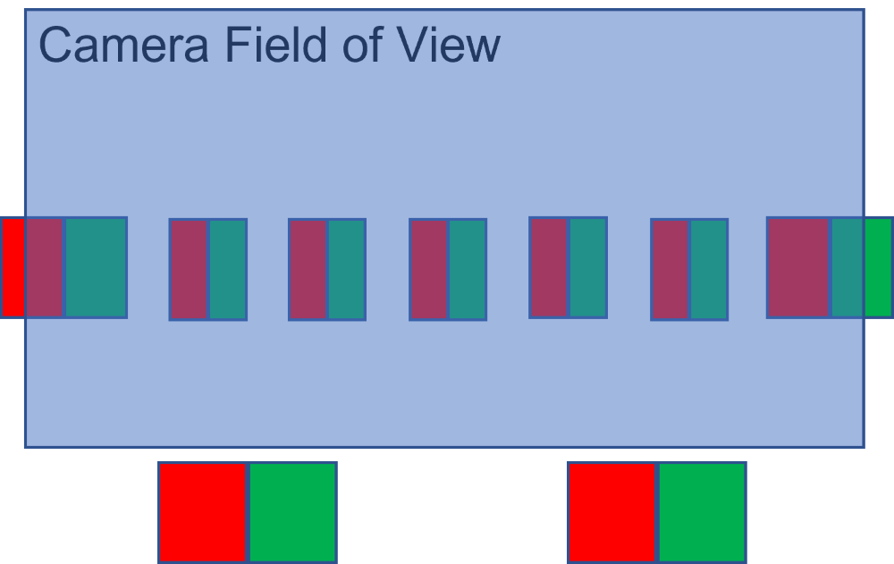
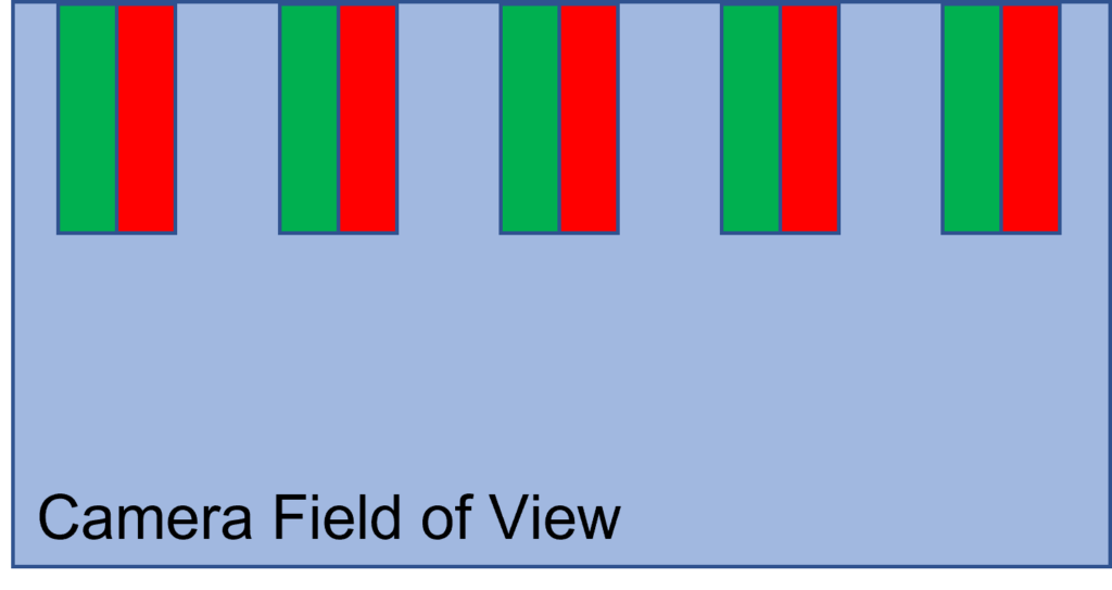
Here are the measured detection zones for the Browning Elite-HP5, Exodus Lift 2, Bushnell Core DS-4K, and Stealthcame DS4K-Ulitmate cameras. I used the first method for the first three cameras, and the second method for the Stealthcam model, which does not have an IR test mode. I have applied some artistic license to the raw data for each camera to simplify the drawings. Note that because the camera sensor and PIR sensor use different optical paths, the only thing that keeps the camera field of view aligned with the PIR sensor detection zones are the mechanical manufacturing tolerances of the camera. I would be surprised in camera manufacturers test this alignment, so it is likely that different cameras will differ from the ideal configurations shown below.
Video Example
Here is an updated video showing the detection zones in action in captures of bears in Massachusetts. Note that the swimming bear captured by the Browning is moving quite quickly, so although the camera triggered when it was off the frame to the left, the video starts with the bear in the center of the frame. The second capture, on an Exodus Lift 2, features a bear moving more slowly as it uses rocks to cross a stream. Here, the animal is much closer to the original trigger point when the video starts.
Practical Guidelines Based on Trail Camera Detection Zones
Based on this data for a few different camera models, here are some general guidelines.
Horizontal Movement
All of the trail camera PIR patterns I’m aware rely on horizontal movement of the target across the field of view. I.e. from left to right, or right to left. If you are missing animals traveling in front of your camera, try adjusting the camera position relative to the typical path of animals to get more horizontal motion.
No Detection Above the Horizon
Two of the sensor patterns I’ve looked have detection zones in the lower 2/3 of the frame. This allows the camera to ignore heat motion which occurs above the horizon — like birds, planes, clouds (or Superman, if he’s airborne). This scheme works for most sets, but if you find yourself in unusual circumstances, make sure consider how to set the camera so the animal movement takes place in the lower 2/3 of the trail camera field of view.
I did find that the detection zones in the Bushnell DS-4K were in the upper 1/3 of the frame. This is surprising. Not sure if this was a conscious design choice by the manufacturer, an oversight, or the result of manufacturing issues. If you use this camera and are missing foreground action, this could be the problem.
Detections Off Camera
Note that the the far left and far right detection zones on the Browning camera are outside the camera’s field of view. This is good if the animal is walking across the field of view — as the camera can trigger as the animal is entering the scene. Similarly, the Exodus has two detection zones apparently below the field of view, which might capture an animal walking into the frame from the bottom diagonally towards the field of view. However, these “out of field of view” detections can also lead to empty photos, if the animal never quite makes it into the camera’s field of view.
Simpler Detection Zones Better?
Notice that the Browning camera has fewer detection zones — only 3; vs. the 8 in the Exodus Lift2. In our experience with these two camera models, the Browning cameras seem more likely to correctly detect an animal. On the flip side, they also seem more prone to false triggering. Given the large capacities of current SD cards, and relatively long battery lives, we generally prefer this tradeoff, even though it occasionally means an SD card full of false triggers.
Summary
I have attempted to give a more subtle, and more accurate description trail camera detection zones. Although the number of such zones can be ascertained by visually examination of the Fresnel lens itself, such an inspection will not give the structure of the detection zones relative to the camera’s field of view. I have described a method I used to figure out this structure. The method is easy to reproduce and will work with trail cameras that have an “aim test” LED. Based on this method, I give the measured structure for a recent Browning, Exodus, and Bushnell trail camera models.
Acknowledgements
Thanks to Pat Blanzy and ChrisW for closely reading my original post Deep Tech: Trail Camera PIR Sensors, and asking, “how did you get the detection zones for these cameras?”. Also to Peter Apps for suggesting the second measurement, which I have fleshed out in an udpate to the original post.
References
- “How do passive infrared triggered camera traps operate and why does it matter? Breaking down common misconceptions,”
Dustin J. Welbourne,Andrew W. Claridge,David J. Paull,Andrew Lambert - Peter Apps, John Weldon McNutt, “How camera traps work and how to work them,” African Journal of Ecology, 2018.
- Peter Apps and John McNutt, “Are camera traps fit for purpose? A rigorous, reproducible and realistic test of camera trap performance“: Critical look at trail camera PIR triggering performance, including use of a cooperative dog to reproducibly evaluate trail camera trigger accuracy.
- Swann, Don & Hass, Ph.D., Christine & Dalton, David & Wolf, Sandy. (2004). Infrared-Triggered Cameras for Detecting Wildlife: An Evaluation and Review. Wildlife Society Bulletin. 32. 357-365. 10.2307/3784976.

Thanks for this article. I’m not a “techy” person, so some of it is way beyond my comprehension.(ha ha)
I’d like to understand what you mean in the example video using the Browning camera. You show on the video where the camera was triggered (at the far right, perhaps even before the bear entered the field of view), but the camera didn’t start recording until the bear was in the water. When a camera is triggered, I thought it automatically started the video or took a photo. Is this not the case?
I’m wondering if maybe the camera is triggered, but because the animal is moving at a fast pace, the camera doesn’t pick up the animal until it’s directly in front of the camera. I’ve noticed this with some of my cameras. A camera will pick up an animal as soon as it enters the field of view and the same camera won’t pick up an animal until it’s right in front of the camera.
Having said all this, I’m wondering if it’s more the speed of the animal passing by the camera than it is the detection zone that affects when the camera triggers, i.e., starts recording video or taking photos.
Thanks,
Mary Beth Pongrac
I was just about to answer “Trigger Delay” : the time it takes between when the PIR sensor detects an animal, and the first frame of the video. In this camera, about a half a second.
This was my assumption when I originally wrote the post. However, on reviewing the video more closely, it’s not right 🙁
Although this bear is swimming impressively fast, she most likely doesn’t make it from the detection zone on the right, to the center of the frame in half a second. In the video it takes her about 4 seconds to get from the center of the frame to the left bank.
The more likely scenario, is that the center detection zone on this particular camera is higher in the frame than I’ve indicated, and the that bear triggers the camera somewhere just right of center.
I’ll update the text to reflect this (more likely) interpretation. Thanks for your thoughtful comment which prompted this correction!
Thank you. That makes sense.
When camera companies advertise their trigger speeds, for example 0.1 seconds, are they basing this number on the detection zone (when the PIR detects an animal) and not the point in which the camera starts filming?
For reputable trail camera companies, the advertised “trigger” speed refers to the time between when the PIR sensor detects a target, and the first frame of video or first photo is recorded. There’s a lot that goes on inside the camera in this critical time. I know, for example, the Browning camera firmware actively tracks the millisecond level timing of their firmware between trigger and photo/video, and it meets their specs. Note that trigger speeds for photos and videos may be different. If different, the video trigger speed is usually slower. Photo/Video variation is generally the source of marketing shorthand like: “Trigger Speed: 0.1 – 0.7 Seconds”. Trailcampro.com measures these values in their reviews.
Pingback:Inside the Browning Recon Force Elite HP4 (BTC-7E-HP4) - Winterberry Wildlife
Pingback:Inside the Bushnell Core DS 4K Trail Camera - Winterberry Wildlife
Pingback:Inside the Stealth Cam DS4K Trail Camera - Winterberry Wildlife
I’m in the process of building a device to do something very similar to what you’ve done here. My goal is to develop a series of tests to compare various camera models that we are considering using in a number of wildlife studies. Finding and recording the PIR detection zones is one of the tests I’m wanting to perform.
If there’s an opportunity to have Bob Zak contact me via email, I would really appreciate it.
Thank you
Pingback:Browning Spec Ops Elite HP5 Teardown - Winterberry Wildlife
Hello. Thanks to your valuable work, I now finally understand why the camera does not always activate or starts differently. I use SPEC OPS ELITE HP5 cameras. If you want, you can analyze my videos for future work https://www.facebook.com/media/set/?set=a.1846191945518855&type=3 It would be really good if we could stick the working areas of the PIR sensor on a transparent film on the LCD display to set the angle correctly. Sorry for my bad English.
That’s a great body of work! Regarding detection zones, that’s a great idea!! I am currently working on a project which will overlay the detection zone on the preview screen. Stay tuned for the next major release which will include this feature.