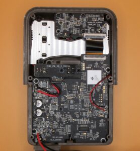
Deep Tech: Hacking Trail Camera Firmware 1 — Overview
This post is an introduces a series of “Deep Tech” articles on hacking (reverse engineering) trail camera firmware. The goal of this reverse engineering project has been to add new features to multiple Browning Trail camera models, as well as to debug and apply fixes to firmware bugs. For examples of results, see posts based on this work: IR to White Flash Trail Camera Conversion, Adding Features to Browning Elite HP5 Firmware, New Optional Features for Browning HP5 Trail Cameras, New Features for Browning Recon Force and SpecOps Cameras, and Deep Tech: Repairing EEPROM in Browning Trail Cameras, and Fixing Browning Edge, Elite HP4 and HP5 SD Card Corruption

In this series, I will give background and explanation of a set of tools I developed along the way. These tools are available on my GitHub site. I will also explain how I used Ghidra, a powerful open source reverse engineering tool, to disassemble, decompile, and annotate the firmware from several generations of cameras. Unfortunately, I am not able to provide open source access to this (albeit critical part) of the firmware reverse engineering solution in order to respect the copyright on camera source code. Still, with the overall process laid out, anyone interested can, in principle, independently reproduce this work.
In the rest of this post, I will introduce topics which will be covered in separate posts in the series.
Requirements
There are many possible goals for any hacking project. When I started this project, my goals were modest. I wanted to convert an IR flash camera to white flash so that it could take color photos at night. Based on some early experiments, I optimistically guessed that I might be able to accomplish my goal simply. Perhaps by modifying a single key instruction in the firmware — say the one which switched between daylight and night time mode — and I would achieve my goal. This guess turned out to be wildly optimistic. It quickly became clear that such a simple approach would not work. Even if such a single instruction existed, I would need to be able to figure out where it was in the overall firmware image. As importantly, I would need to somehow get it into a firmware image that I could load into the camera.
This upcoming post on Deep Tech: Hacking Trail Camera Firmware 2 — Requirements will focus on the requirements. I will also list some “non-requirements” that help bound the problem.
Business Considerations
Readers of this blog sometimes comment, “I wish Browning would allow customization,” or “I wish Browning would support improvement XYZ”. In this upcoming post Deep Tech: Hacking Trail Camera Firmware 3 – Business Considerations, I will speculate on the reasons that firmware customization is not typical in the trail camera market. I will also note exceptions. No one will be surprised that these reasons are grounded in the business models and financial interests of several companies (and types of companies) involved in making, marketing, selling, and supporting trail cameras.
Trail Camera Theory of Operation
To understand the details of a hacking project, it’s critical to understand the basics of how the target system works. In the Deep Tech: Trail Camera Firmware Hacking — Theory of Operation post, I will document what I found out to give readers a framework for understanding the technical context of the reverse engineering flow.

Reverse Engineering Tools
The key to any computer project is a set of tools tailored to solve specific aspects of the overall task. Because these tools are small projects in their own right, I dedicate a post to each.
Reverse Engineering Flow
As with any complex engineering project, it is important to break down a complicated process into a series of steps, or, a “recipe”, if you will. In the post Deep Tech: Trail Camera Firmware Hacking — Reverse Engineering Flow I will cover a set of steps I have used to reverse engineer the firmware in several models of Browning Trail cameras. With benefit of hindsight, I will focus on what has worked, and leave out a series of ultimately unproductive steps. This flow is largely laid out in a Colab worksheet, making it easy to pull together 3rd party and external tools, into cloud execution environment. See: “Deep Tech: Trail Camera Firmware Hacking — Tool Flow”
New Functions — Source Code Overview
In several past posts, I describe new functions that I have added to some Browning Trail camera models. See:Adding Features to Browning Elite HP5 Firmware, New Optional Features for Browning HP5 Trail Cameras. In this post, I will give an introduction to the source code I wrote to implement these features. See: “Deep Tech: Trail Camera Firmware Hacking — Source Code Overview”
Up Next
This post is a set of “coming attrractions” for more detailed posts to come. These posts will document the deep technology involved in reverse engineering and subsequently hacking of trail camera firmware.
I realize the audience for this particular series is small. Yet it seems worthwhile to share these learnings with the small set of possibly interested parties. These may include researchers, trail camera enthusiasts, and (perhaps even) trail camera manufacturers. As I have discovered, there is both an interest in customizing trail camera firmware on the part of consumers and researchers. There are also good reasons why trail camera companies themselves are unlikely to do this. Thus, this work may address a long term niche.
Feedback
The rate at which I make it through this series, and the amount of detail in each post will depend, to some extent, on feedback from readers. Please comment below if you’d like to see more faster.

I was a software developer for the business software the company used and I would put in options frequently to let the user choose. So, often in products and software I use, I run into situations of why are there not more options.
Thank you for adding features that trail camera users can utilize.
You’re welcome! I can see why a company would restrict the number of options: increased development time/$; increased testing time/$$; increased tech support time/$$. If the new feature doesn’t bring in more money then it costs, it doesn’t get done. That’s business. I worked at a company that spent an enormous amount of time and $$ figuring out whether a new feature made business sense, or not. It’s exhausting! It’s more fun these days to add features that are useful for folks who are doing cool work, but who have very limited budgets. Still, there will come a time when then bathtub curve catches up to me, and this won’t be practical any more.
Bob,
Can I first say how generous it is of you to publish all the information on these cameras.
I have a BTC7e camera that has two faults :-
1. It loses data and time whenever a reset occurs. I have replaced the supercapacitor ( corroded ,2.7 volt charge through D4 from 3v3), removed ( using low temperature solder) the 25 series flash reprogramed it with the image from Github, run the diagnostic ( left tight and mode held during power up) on the rtc and it works. I can also see the rtc work by staying within the setup menus for more than i minute and returning to date and time set.
I cannot find the rtc chip on the board to check the supply and back up voltage.
Can you help
2. The leds under the buttons do not come on despite all being ok using a DVM in diode mode and being supplied with 3v3.
Adding the numbers of the chips on the boards would be very helpful as manufacturers temp to try and reuse pcb layouts and components. They are all easy to replace with chip quik low temperature solder and good flux.
For instance the 20 pin ST-866 I cannot find easily.
Wow — a man after my own tech heart 🙂
1. Lost Data: Just so I understand — you removed the factory EEPROM (by desoldering), then reprogrammed it withe image from my GitHub site; then soldered the same part back in?
First of all — good job! I’ve never been able to reuse an EEPROM I’ve desoldered. But you may have been hoist by your own desoldering skill. The failure mode I’ve seen in these EEPROMs is that they lose the ability to write new data. Thus, they still “work”, since the old data (program and settings) can be read, but they can’t accept any new settings. This also means they can’t be reprogrammed. I’m surprised that your programmer didn’t complain about programming errors? I’m also surprised that if it was able to reprogram the device, that it would work, since the EEPROM images on my Github site are specific to the MX25L12835FM21-10G (that is not the same as the factory EEPROM) (The boot loader checks the EEPROM device id and compares it to the value stored in the firmware before downloading the rest of the EEPROM). Net, net. I would remove the current EEPROM, throw it away, and install a new MX25L12835FM21-10G programmed with the correct image.
2. LEDs: It’s possible that the EEPROM lost the bits that turn the LED on, and that replacing the EEPROM will also fix the LED probem. We can only hope. I haven’t looked at this circuit, but for sure it’s controlled by firmware, which means there’s an activation signal in there somewhere. It’s possible that the route to the signal has been damaged somewhere along the line by a little moisture incursion. I would start by using a meter with some very sharp probes and some good magnifying optics to trace the path on both legs of the LED as far back as possible, looking for trace or connector damage.
3. I’ll see what I can do about putting up a per-model “BOM decoder”. Not sure when I’ll get to this. In the meantime, I believe that the part marked “ST-866” is an ultra low power 8-bit microcontroller used as a boot controller for the main SOC. It likely has some factory code burned into it, making it very difficult to source. 🙁
Keep us posted on how you make out.
-bob
Hi folks have a few btc-7e-hp4 that need LCDs has anyone a link to a replacement
Many thanks
See https://winterberrywildlife.ouroneacrefarm.com/2021/06/30/how-some-trail-cameras-fail/#lcd-failure